40
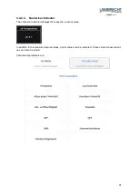
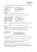
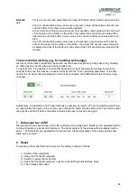
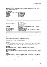
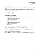
For each digital output can firstly be set, whether it should be “high“ or “low“ in the normal situation
(default situation).
If the switch is set to “low“ the corresponding output also remains at logical 0 at “low“ and at logical 1
at “high“.
If the switch is set to “high“ the corresponding output also remains at logical 0 at “high“ and at logical 1
at “low“.
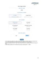
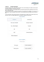
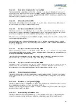
For each warning channel following parameters can be adjusted
•
The to be monitored parameter
•
Alert threshold:
o
Low level = lower switching threshold
o
High level = upper switching threshold
•
Window function or hysteresis function
•
Energy and drop-out delay
•
Time-dependent warnings (time window with start-time, stop-time, weekdays)
•
Duration of a warning
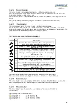
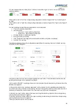
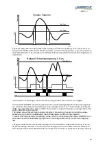
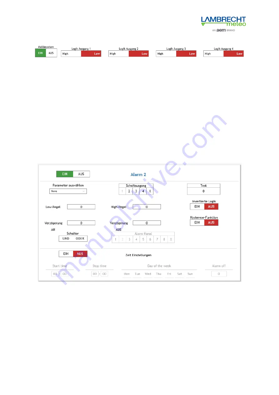
The following diagram shows the configuration possibilities of a warning channel. In total 8 warning
channels can be configured.
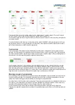
The warning channels can be connected logically with each other. Therewith also wind direction de-
pending on warnings can be realized for example.
Via the switch „ON/OFF“ a warning channel can be activated. Deactivated warning channels have the
default value logical-0.
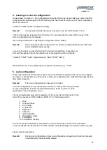
In the selection field „to be monitored parameter” will be chosen from the available parameters that
one which has to be monitored in this warning channel. Through the selection of the parameter simul-
taneously is defined the unit with which the „low level“ and „high level“ are adjusted.
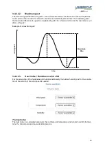
In the field „low level“ will be entered the lower switching threshold beyond which the corresponding
warning channel will be set to logical-1.
In the field „high level“ will be entered the upper switching threshold beyond which the corresponding
warning channel will be set to logical-0.
Thereby window functions can be realized.

