Simple Logger
®
II (Bluetooth Edition) Series
9
2.2
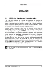
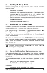
Control Features
Overload (1)
Stand-By (1)
Recording (2)
Empty (0)
Partial (1)
Full (2)
Low Battery
Triggered (1)
Active (2)
Enabled (1)
STOP
RECORDING
ALARM
MEMORY
BLUETOOTH
START
CONTROL
STATUS
ERASE
ON/OFF
CLEAR
600V CAT IV
2
1
3
4
DISCONNECT ALL INPUTS BEFORE
OPENING BATTERY COMPARTMENT
5
4
1
2
6
7
3
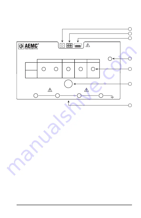
Figure 2-1
1. Reset Switch
The
RESET
switch resets the CPU. To access this switch,
discon-
nect
all inputs and remove the battery compartment cover. The reset
switch is located on the exposed PCB (refer to § 3.10).
2. Flash Upgrade Switches
These three switches (accessible from under the battery cover), the
RESET
switch and upgrade software are used to recover from a failed
flash upgrade procedure (refer to § 3. 1).
3. Female Type Mini-B USB Connector
This connector is located under the battery cover and is used for per-
forming firmware upgrades when available
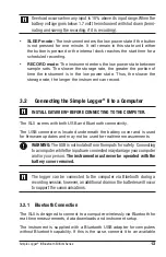
4. Low Battery Indicator
The instrument contains protection circuitry to prevent it from being
turned on when the battery voltage is below 1.7V.

