background image

Simple Logger

®

 II (Bluetooth Edition) Series


13


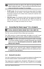
Overload occurs when any input is 10% above its input range. When the 
battery voltage goes below 1.7 volt the instrument will shut down (termi-
nating and saving the recording, if it is recording).

SLEEP mode:

 The instrument enters the low power state if the button

is not pressed for one minute. It will remain in this state until either

the button is pressed or the internal clock reaches the start time for a

scheduled recording.

RECORD mode:

 The instrument enters the low power state between

sample sets. The slower the storage rate, the greater the portion of

time the instrument is in the low power state. Thus, the slower the

storage rate, the longer the instrument can record.

3.2 

Connecting the Simple Logger

®

 II to a Computer

INSTALL DATAVIEW

®

 BEFORE CONNECTING TO THE COMPUTER.

The SLII comes with both USB and Bluetooth connectivity.
The USB connector is located underneath the battery cover and is used 

for firmware updates and may not be used for realtime measurements

WARNING: 

The USB is not isolated from the inputs for safety.  Connecting 

to a computer while the inputs are connected may damage your computer 
and/or your person. 

The instrument must never be operated with the 

battery cover removed.

The logger can be connected to the computer via Bluetooth during a 
recording session, however, an additional drain on the batteries will occur 
to support the communications.

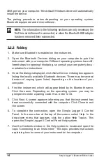
3.2.1  Bluetooth Connection

The SLII is designed to connect to a computer wirelessly via Bluetooth for 

real-time measurements, data downloads and instrument setup.
The instrument is supplied with a Bluetooth USB adapter for computers 

without Bluetooth capability. If this is the case, connect it to an available 

Summary of Contents for 2126.10

Page 1: ...E N G L I S H User Manual AC CURRENT AC DC VOLTAGE AC VOLTAGE Simple Logger II Data Loggers Bluetooth Edition...

Page 2: ......

Page 3: ...ir and calibration facility for a nominal charge The recommended calibration interval for this instrument is 12 months and begins on the date of receipt by the customer For recalibration please use ou...

Page 4: ...necting the Simple Logger II to a Computer 13 3 2 1 Bluetooth Connection 13 3 2 2 Pairing 14 3 3 Turning Bluetooth ON OFF 15 3 4 Recording Data 15 3 4 1 Starting a Recording Session 15 3 4 2 Stopping...

Page 5: ...E INSTALLATION 23 4 1 Installing DataView 23 4 2 Simple Logger II Control Panel 25 5 MAINTENANCE 26 5 1 Replacing the Batteries 26 5 2 Cleaning 26 6 SPECIFICATIONS 27 APPENDIX TROUBLESHOOTING 33 APPEN...

Page 6: ...al to those of the instrument Observe the environmental conditions of use Do not modify the instrument and use only original replacement parts Repairs or adjustments must be performed by authorized pe...

Page 7: ...Battery Fuse USB socket Compliance with the Low Voltage Electromagnetic Compatibility European directives 73 23 CEE 89 336 CEE In the European Union this product is subject to a separate collection s...

Page 8: ...ual Simple Logger II Model L264 Cat 2126 23 4 Channel TRMS Bluetooth 600VAC DC Includes Bluetooth USB adapter set of 5 color coded 4 red 1 black 5 ft leads with color coded alligator clips twelve colo...

Page 9: ...g Bag Cat 2133 72 Replacement Set of 12 Color coded Input ID Markers Cat 2140 45 Lead Replacement Set of 3 Color coded Red Black White 5 ft with Color coded Alligator Clips L564 Cat 2152 03 Lead Repla...

Page 10: ...ate of up to eight times per second Samples are taken at a user defined storage rate This means that the input s are ignored between measurement intervals The SLII s battery operation allows operation...

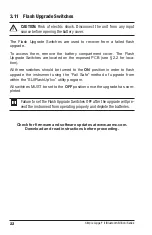
Page 11: ...tch discon nect all inputs and remove the battery compartment cover The reset switch is located on the exposed PCB refer to 3 10 2 Flash Upgrade Switches These three switches accessible from under the...

Page 12: ...peration when holding down the button is indicated with text above each LED The status indication when the button is not being held down associated with each LED is indicated with text below each LED...

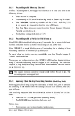
Page 13: ...e control LED corresponding to the desired operation lights Releasing the CONTROL button when the desired control LED is illuminated results in the corresponding operation being performed When pressin...

Page 14: ...US OFF No alarm has been seen on any input Single blink At least one channel has seen an alarm at least once Double blink At least one channel is currently in an alarm condition Fast blink Armed to cl...

Page 15: ...mputer INSTALL DATAVIEW BEFORE CONNECTING TO THE COMPUTER The SLII comes with both USB and Bluetooth connectivity The USB connector is located underneath the battery cover and is used for firmware upd...

Page 16: ...ick Add a Device A dialog box appears listing the locally available Bluetooth devices There may be several devices of varying types listed depending on the location of your computer 4 Find the instrum...

Page 17: ...d see 4 Once a configuration is written to the instrument it will no longer need to be connected to DataView to start the scheduled recording When data is stored in the memory the user may download th...

Page 18: ...omputer 3 5 Downloading Recorded Data Recorded measurements stored in the instrument are transferred to a computer via the download command in the Simple Logger II Control Panel 3 6 Clearing Alarm Ind...

Page 19: ...t the erase operation During the erase operation the LED will blink once every second Erasure takes about 1 minute to complete If the button is not pressed within five seconds of arming the erase oper...

Page 20: ...format using the Configure Instrument dialog box in the Simple Logger II Control Panel software Control Panel trend measurements are stored at this fixed storage rate 3 9 Logger Operation When the in...

Page 21: ...nds prior to starting a New Recording Session the memory is partially full To save clear or check memory availability use the Simple Logger II Control Panel software There may be instances where the G...

Page 22: ...ument refer to 5 1 Replacing the batteries while the unit is in SLEEP mode will not result in the loss of data memory The internal backup capacitor will maintain the clock and memory while the batteri...

Page 23: ...ended to reset the instrument when the logger is recording downloading or being configured If the logger is not responding to a button press make sure the unit has sufficient battery power If the batt...

Page 24: ...the exposed PCB see 2 2 for loca tion All three switches should be turned to the ON position in order to flash upgrade the instrument using the Fail Safe method of upgrade from within the SLIIFlashUp...

Page 25: ...our computer If Autorun is enabled an AutoPlay window appears on your screen Click Open folder to view files to display the DataView folder NOTE If Autorun is not enabled or allowed use Windows Explor...

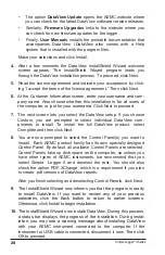
Page 26: ...select individual DataView com ponents to install To install the full DataView product select Complete and then click Next 8 You are now prompted to select the Control Panel s you want to install Each...

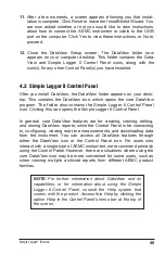
Page 27: ...the Simple Logger II Control Panel icon Clicking this icon opens the Simple Logger II Control Panel In general core DataView features are for creating viewing editing and storing DataView reports whi...

Page 28: ...eplace the four 1 5V C cell LR14 alkaline batteries the backup capacitor provides backup power for approximately 10 seconds while the main batteries are being changed Replace the cover and the screws...

Page 29: ...mory and retained even if battery is low or removed Communication Bluetooth Class 2 Power Source 4x1 5V C cell alkaline batteries Battery Life 200hrs at 125ms up to 180 days dependent on storage rate...

Page 30: ...ss 2 Power Source 4x1 5V C cell alkaline batteries Battery Life 200hrs at 125ms up to 180 days dependent on storage rate recording length MECHANICAL Dimensions 5 904 x 5 904 x 3 568 150 x 150 x 91mm w...

Page 31: ...ble using DataView Memory 1 000 000 measurements 2MB Recorded data is stored in non volatile memory and retained even if battery is low or removed Communication Bluetooth Class 2 Power Source 4x1 5V C...

Page 32: ...ore on Alarm Recording Length 15 minutes to 8 weeks programmable using DataView Memory 1 000 000 measurements 2MB Recorded data is stored in non volatile memory and retained even if battery is low or...

Page 33: ...1m ENVIRONMENTAL Operating Temperature 14 to 122 F 10 to 50 C Storage Temperature 4 to 140 F 20 to 60 C Relative Humidity Up to 85 at 95 F 35 C Non condensing Altitude 2000m SAFETY ELECTRO MAGNETIC CO...

Page 34: ...0mm Safety EN 61010 2 032 Pollution Degree 2 300V CAT IV 600V CAT III NOTE Currents 0 5A will be displayed as zero Neutral current measures down to 0A Model MN193 Nominal Range 5A and 100AAC Measureme...

Page 35: ...ng If it is memory is full and you need to erase the data see 3 7 Make sure the SLII is properly configured so that you have Storage Rate Recording Period and at least one Measurement Channel specifie...

Page 36: ...rocess of transferring data from the logger to the computer Hz Hertz a unit of measure of frequency equivalent to cycles per second I O Input output a device or port capable of sending or receiving di...

Page 37: ...cludes calibration certificate plus recorded calibration data Ship To Chauvin Arnoux Inc d b a AEMC Instruments 15 Faraday Drive Dover NH 03820 USA Phone 800 945 2362 Ext 360 603 749 6434 Ext 360 Fax...

Page 38: ...s for repair provided we have your warranty registration information on file or a proof of purchase AEMC Instruments will at its option repair or replace the faulty material REGISTER ONLINE AT www aem...

Page 39: ......

Page 40: ...07 17 99 MAN 100357 v8 Chauvin Arnoux Inc d b a AEMC Instruments 15 Faraday Drive Dover NH 03820 USA Phone 603 749 6434 Fax 603 742 2346 www aemc com...

Reviews: