6
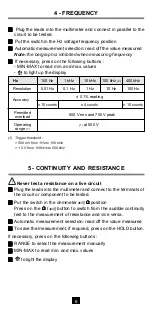
4 - FREQUENCY
!
!
!
!
!
Plug the leads into the multimeter and connect in parallel to the
circuit to be tested.
!
!
!
!
!
Put the switch in the Hz voltage frequency position
!
!
!
!
!
Automatic measurement selection: read off the value measured
Note : the bargraph is inhibited when measuring frequency
!
!
!
!
!
If necessary, press on the following buttons :
- MIN-MAX to read min. and max. values
-
to light up the display
Hz
100 Hz
1 kHz
10 kHz
100 kHz
(2)
400 kHz
Resolution
0.01 Hz
0.1 Hz
1 Hz
10 Hz
100 Hz
Accuracy
± 0.1% reading
± 10 counts
± 4 counts
± 10 counts
Permitted
500 V rms and 750 V peak
overload
Operating
(1)
at 500 V
range
(1)
(1) Trigger threshold :
> 500 mV from 1 Hz to 100 kHz
> 1.5 V from 100 kHz to 500 kHz
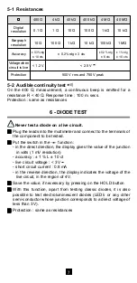
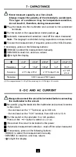
5 - CONTINUITY AND RESISTANCE
Never test a resistance on a live circuit
!
!
!
!
!
Plug the leads into the multimeter and connect to the terminals of
the circuit or component to be tested.
!
!
!
!
!
Put the switch in the ohmmeter
Ω
Ω
Ω
Ω
Ω
position
Press on the
Ω
Ω
Ω
Ω
Ω
/
button to switch from the audible continuity
test to the measurement of resistance and vice versa.
!
!
!
!
!
Automatic measurement selection: read off the value measured
!
!
!
!
!
To save the measurement, if required, press on the HOLD button.
If necessary, press on the following buttons :
!
!
!
!
!
RANGE to select the measurement manually
!
!
!
!
!
MIN-MAX to read min. and max. values
!
!
!
!
!
to light the display


