background image

Simple Logger® Temperature Module Model L605 

11


CHAPTER 5

MAINTENANCE

5.1 

Battery Installation

Under normal conditions, the battery will last up to a year of continuous 

recording unless the logger is restarted very frequently.
In the OFF mode, the logger puts almost no load on the battery. Use the 

OFF mode when the logger is not in use. Replace the battery once a year 

in normal use.

If the logger will be used at temperatures below 32°F (0°C) or is frequently 

turned on and off, replace the battery every six to nine months.

1. Make sure your logger is turned off (no blinking light) and all inputs

are disconnected.

2. Turn the logger upside down. Remove the four Phillips head screws

from the base plate, then take off the base plate.

3. Locate the two-wire (red/black) battery connector and attach the 9V

battery to it. Make sure that you observe polarity by lining up the

battery posts to the proper terminals on the connector.

4. Once the connector is plugged onto the battery, insert the battery

into the holding clip on the circuit board.

5. If the unit is not in record mode after installing the new battery, dis

-

connect it and press the button twice then reinstall the battery.

6. Reattach the base plate using the four screws removed in Step 2.

Your logger is now recording (LED blinking). Press the 

PRESS

 button for 

five seconds to stop the instrument.

NOTE:

 For long-term storage, remove the battery to prevent discharge 

effects.

5.2 

Cleaning

The  body  of  the  logger  should  be  cleaned  with  a  cloth  moistened  with 

soapy water. Rinse with a cloth moistened with clean water. Do not use 

solvent.

Summary of Contents for L605

Page 1: ...SIMPLE LOGGER TEMPERATURE MODULE L605 E N G L I S H User Manual...

Page 2: ...he case Please record this number and purchase date for your records SIMPLE LOGGER MODEL L605 CATALOG 2114 17 SERIAL _ _______________________________________________ PURCHASE DATE ___________________...

Page 3: ...ctrical Specifications 6 3 2 Mechanical Specifications 7 3 3 Environmental Specifications 7 3 4 Safety Specifications 7 4 OPERATION 8 4 1 Software Installation 8 4 2 Recording Data 9 4 3 Using the Sof...

Page 4: ...nstrument while connected to any circuit or input ALWAYS inspect the instrument and lead prior to use Replace any defective parts immediately NEVER use the Model L605 on electrical conductors rated ab...

Page 5: ...ment appears to be damaged file a claim immediately with the carrier and notify your distributor at once giving a detailed description of any damage Save the damaged packing container to substantiate...

Page 6: ...gger Single Blink STAND BY mode Double Blink RECORD mode Continuously On OVERLOAD condition No Blinks OFF mode 1 2 3 4 1 Start Stop Button 2 Inline Connector for External Sensor 3 LED Indicator 4 RS 2...

Page 7: ...ht side of the logger has a female 9 pin D shell serial connector used for data transmission from the data logger to your computer 2 3 Mounting Your Simple Logger is equipped with mounting holes in th...

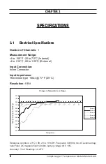
Page 8: ...Impedance Thermistor type 10k 77 F 25 C Resolution 8 Bit Change in Temperature vs Range 9 00 8 00 7 00 6 00 5 00 4 00 3 00 2 00 1 00 0 00 1 00 2 00 2 5 1 5 5 5 1 5 2 5 3 5 4 5 5 5 6 5 7 5 8 5 9 5 Tem...

Page 9: ...nnector 1200 Bps 3 2 Mechanical Specifications Size 2 7 8 x 2 5 16 x 1 5 8 73 x 59 x 41mm Weight with battery 5 oz 140g Mounting Base plate mounting holes or Velcro pads Case Material Polystyrene UL V...

Page 10: ...each stored file One 9 pin serial port one parallel port for printer support CD ROM drive 1 Insert the Simple Logger CD into your CD ROM drive If auto run is enabled the Setup program will start autom...

Page 11: ...n of the Set up window then select Simple Logger Version 6 xx in the Options section 4 Click the Install button and follow the on screen prompts to install the software 4 2 Recording Data If the tempe...

Page 12: ...software automati cally detects the baud rate the logger will communicate with the computer ID number of the logger and number of points recorded displayed 4 3 1 The Function Command The Function com...

Page 13: ...ase plate then take off the base plate 3 Locate the two wire red black battery connector and attach the 9V battery to it Make sure that you observe polarity by lining up the battery posts to the prope...

Page 14: ...ble click on the desired file to open the Text Import Wizard 5 Review the selections in the first wizard screen and make sure that the following choices are selected Original Data Type Delimited Start...

Page 15: ...Click on column B at the top of the column to select the data then click on Insert from the main menu and select Columns from the drop down menu 2 Next click on column A at the top of the column to s...

Page 16: ...Time option from the category list on the left Select the time format you desire and click on OK to format the column FigureA 2 shows a typical spreadsheet with date time and value displayed It may be...

Page 17: ...T Includes calibration certificate plus recorded calibration data Ship To Chauvin Arnoux Inc d b a AEMC Instruments 15 Faraday Drive Dover NH 03820 USA Phone 800 945 2362 Ext 360 603 749 6434 Ext 360...

Page 18: ...eriod you may return the in strument to us for repair provided we have your warranty registration information on file or a proof of purchase AEMC Instruments will at its option repair or replace the f...

Page 19: ......

Page 20: ...08 18 99 MAN 100213 v10 Chauvin Arnoux Inc d b a AEMC Instruments 15 Faraday Drive Dover NH 03820 USA Phone 603 749 6434 Fax 603 742 2346 www aemc com...

Reviews: