background image

V

DC

AC

G


V

Hz 

In the 

MΩ

 settings, the 

 s

ymbol indicates that the voltage is too high (>25V) 

and that insulation measurements are prohibited:

V

DC

AC

G


V

Hz 

If the voltage is >15V, continuity, resistance, and capacitance measurements are 

prohibited.

2.2.2  Insulation Measurement

Insulation measurement results can be affected by the impedances of 
additional circuits connected in parallel or by transient currents. 
Do not start any measurement while the symbol 


is displayed.

1.

Set the rotary switch to one of the 

MΩ

 positions. The test voltage

depends on the voltage of the installation to be tested.

Summary of Contents for Megohmmeters 6522

Page 1: ...Megohmmeters Model 6522 6524 CHAUVIN ARNOUX GROUP ENGLISH User Manual 99 Washington Street Melrose MA 02176 Phone 781 665 1400 Toll Free 1 800 517 8431 Visit us at www TestEquipmentDepot com...

Page 2: ...lished specifications An NIST traceable certificate may be requested at the time of purchase or obtained by returning the instrument to our repair and calibration facility for a nominal charge Serial...

Page 3: ...e Chauvin Arnoux Inc has made every reasonable effort to ensure that this documentation is accurate but does not warrant the accuracy or completeness of the text graphics or other information containe...

Page 4: ...instrument exceeds regulatory requirements with respect to recycling and reuse Indicates conformity with European directives in particular LVD and EMC Indicates that in the European Union the instrume...

Page 5: ...ee 3 Except for voltage measurements take no measurements on electrically live systems Do not use the instrument if it appears damaged incomplete or poorly closed Before each use check the condition o...

Page 6: ...unction 12 2 1 2 2 Setting an Alarm Threshold 13 2 1 2 3 Viewing Alarms 14 2 1 3 REL Function Model 6524 15 2 1 4 HOLD Function 16 2 1 5 Backlighting 16 2 1 6 Standby Mode 16 2 2 Taking Measurements 1...

Page 7: ...nt 34 3 3 3 Resistance and Continuity Measurement 35 3 3 4 Intrinsic Uncertainty and Operating Uncertainty 36 3 4 Power Supply 36 3 5 Environmental Conditions 36 3 6 Mechanical Specifications 37 3 7 S...

Page 8: ...ier and notify your distributor at once providing a detailed description Save the damaged packing container to substantiate your claim Ordering Information Megohmmeter Model 6522 Cat 2155 51 Megohmmet...

Page 9: ...egohmmeters Models 6522 and 6524 are portable measuring instruments with digital displays They are powered by batteries These instruments can check the safety of electrical installations For example t...

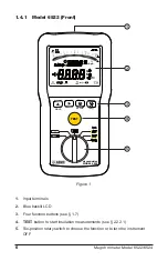
Page 10: ...MEGOHMMETER MODEL 6522 G M VDC AC k M mA A G VHz G M HOLD P ALARM 1 2 3 4 5 Figure 1 1 Input terminals 2 Blue backlit LCD 3 Four function buttons see 1 7 4 TEST button to start insulation measurement...

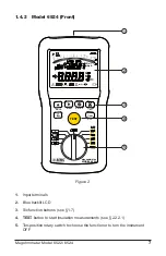
Page 11: ...MMETER MODEL 6524 TEST REL G M VDC AC k ALARM MEM DARPI T1T2 k M mA A G VHz G M HOLD REL P 1 2 3 4 5 Figure 2 1 Input terminals 2 Blue backlit LCD 3 Six function buttons see 1 7 4 TEST button to start...

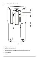
Page 12: ...1 5 Back of Instrument 1 2 3 4 5 Figure 3 1 Captive quarter turn screw 2 Battery compartment cover 3 Mounting magnets molded into instrument case Model 6524 4 Non skid pads 5 Stand...

Page 13: ...ctions 2 2 2 Toggles backlighting ON and OFF 2 1 5 HOLD Freezes unfreezes the displayed measurement on the LCD 2 1 4 SET UP Accesses the instrument s setup parameters and information 2 1 1 0 Applies l...

Page 14: ...thmic bar graph displays insulation measurements 2 Secondary display area 3 Main display area 4 Icons indicators When the measured value is below the minimum the instrument displays When measuring vol...

Page 15: ...the test button 2 1 Setting Up the Instrument 2 1 1 Configuration Settings SET UP 2s A 2 second press of the SET UP button enables you to change configuration settings on the instrument You can then...

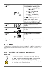
Page 16: ...are version 5th press on Displays the instrument hardware version 6th press on Return to the first press 2 1 2 Alarms The instrument includes an alarm function that sounds an audible buzzer when a def...

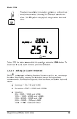
Page 17: ...button To deactivate an active alarm function press the button 2 1 2 2 Setting an Alarm Threshold While is displayed indicating the alarm function is active you can change the alarm threshold by press...

Page 18: ...change its value 4 Use the and buttons to select and change the other digits in the threshold value as well as the units of measurement 5 When finished setting the threshold press the button to valid...

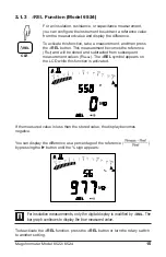
Page 19: ...e stored and subtracted from subsequent measurement values Rmeas The REL symbol appears on the LCD while this function is activated M REL V G If the measured value is less than the stored value the di...

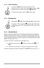
Page 20: ...ute 2 1 6 Standby Mode After 5 minutes of operation with no user activity the instrument automatically switches to standby mode To restore normal operation simply press any button The instrument retur...

Page 21: ...electrical outlet before measuring unknown voltages 1 Set the switch to V or to one of the M positions 100V V k MR OFF 250V 500V 1000V 50V M 2 Using the leads connect the system to be tested to the i...

Page 22: ...and capacitance measurements are prohibited 2 2 2 Insulation Measurement Insulation measurement results can be affected by the impedances of additional circuits connected in parallel or by transient c...

Page 23: ...t VDC 3 Optional Press the button to display the current or the elapsed time You can also do this during the measurement 4 Press the TEST button and hold it down until the displayed measurement is sta...

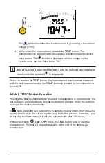
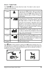
Page 24: ...d until the next measurement or the HOLD button is pressed or the instrument is turned OFF 2 2 2 1 TEST Button Operation Pressing the TEST button starts an insulation measurement In normal mode the te...

Page 25: ...t blinks you can change it using the button Press to go to the next digit and to change it Then press to validate 3rd press PI T1T2 Model 6524 This enables the PI function This is used to calculate th...

Page 26: ...ance at that time Use the following table as a guide for interpreting the results of a DAR or PI test DAR PI Condition of insulation DAR 1 25 PI 2 Poor or even dangerous 1 25 DAR 1 6 2 PI 4 Good 1 6 D...

Page 27: ...fe However the standard IEC 61557 requires 200mA current for continuity testing The Model 6522 can take measurements only at 200mA If an external voltage 15V is detected in the system under test durin...

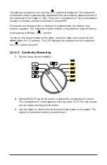
Page 28: ...ompensation must be redone by displaying a blinking symbol To remove the compensation of the leads leave the leads open and press the 0 button for 2 seconds The LCD displays the resistance of the lead...

Page 29: ...continuity value per standard IEC 61557 1 Take a measurement at 200 mA and note its value R1 2 Reverse the leads and note the value R2 3 Calculate the mean 2 2 4 Resistance Measurement Model 6524 Resi...

Page 30: ...the LCD via the HOLD button 2 1 4 The result of a timed test 2 2 2 2 2s MEM To save the measurement press the MEM button for 2 seconds The measurement is stored in the first available record in the i...

Page 31: ...ee the other measurements press the button The record number is decremented and the corresponding measurement is displayed 3 To scroll rapidly through the recorded measurements keep the button pressed...

Page 32: ...etters CLR 4 Press the MEM button for 2 seconds to confirm the deletion To cancel press the CLR button for 2 seconds 2 3 3 2 Deleting All Recordings 1 Set the rotary switch to MR 2 Press the CLR butto...

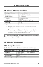
Page 33: ...perating uncertainty includes the intrinsic uncertainty plus variations of the quantities of influence position supply voltage temperature etc as defined in standard IEC 61557 In this section uncertai...

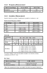
Page 34: ...to 200G Accuracy Test Voltage VT 50V 100V 250V 500V 1000V Measurement Range 10 to 999k and 1 000 to 3 999 M 4 00 to 39 99M 40 0 to 399 9M 400 to 3999M 4 00 to 39 99G 40 0 to 200 0G Resolution 1k 10k 1...

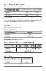
Page 35: ...from VT to 25V the discharge time is 2s F Test Current Maximum test current 2mA Measurement Range 0 01 to 39 99 A 40 0 to 399 9 A 0 400 to 2 000mA Resolution 10nA 100nA 1 A Accuracy 10 R 3 ct Typical...

Page 36: ...e leads the instrument allows display of negative values down to 0 05 at 200 A and 0 5 at 20mA Test current 200mA range 200mA 0mA 20mA 20mA range 20mA 5mA Measurement Range 0 to 250mA Resolution 1mA A...

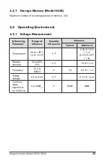
Page 37: ...Measurement Influencing Parameter Range of influence Quantity influenced Influence Typical Maximum Temperature 20 to 55 C 4 to 131 F V F 0 3 R 10 C 1 ct 0 3 R 18 F 1 ct Relative humidity 20 to 80 RH...

Page 38: ...R 1 ct 3 R 2 ct VT 50 to 1000V 1 R 2 ct Measurement current 1 R 2 ct Supply voltage 6 6 to 9 6V M 0 1 R 2 ct 50 60Hz AC voltage superposed on the test voltage VT 50V R 0 1G 4V from 0 1 to 1G 0 2V 5 R...

Page 39: ...20 to 55 C 4 to 131 F at 200mA 2 R 10 C 2 ct at 20mA 2 R 10 C 2 ct R 1 R 10 C 2 ct Relative humidity 20 to 80 RH at 200mA 2 R 1 ct 4 R 2 ct at 20mA 4 R 2 ct R 3 R 2 ct Supply voltage 6 6 to 9 6V at 2...

Page 40: ...n 0 and 35 C 32 and 95 F 3 4 Power Supply The instrument is powered by six 1 5V alkaline AA LR6 batteries The voltage range ensuring correct operation is from 6 6V to 9 6V Typical life between charges...

Page 41: ...ress protection IP 54 per IEC 60529 not in operation IK 04 per IEC 50102 Drop test per IEC 610 3 7 Safety Standards Safety according to EN 61010 2 30 2010 Insulation Class 2 Pollution Degree 2 Overvol...

Page 42: ...t completely and turn the rotary switch to OFF Use a soft cloth dampened with soapy water Rinse with a damp cloth and dry rapidly with a dry cloth or forced air Do not use alcohol solvents or hydrocar...

Page 43: ...eads or accessories from the instrument and turn the rotary switch to OFF 2 Use a tool or a coin to turn the quarter turn screw of the battery compartment cover 3 Remove the battery compartment cover...

Page 44: ...ment the instrument measures voltage on the system under test If it detects voltage in excess of 25V and you attempt to take a measurement the instrument displays the message shown to the left and no...

Page 45: ...voltage in excess of 15V AC or DC it interrupts the measurement and displays the screen show to the left You must eliminate the voltage to resume the measurement 4 2 1 4 Memory full Model 6524 MEM Whe...

Page 46: ...e have your warranty registration information on file or a proof of purchase AEMC Instruments will at its option repair or replace the faulty material 4 6 Warranty Repairs What you must do to return a...

Page 47: ...CHAUVIN ARNOUX GROUP 04 16 99 MAN 100429 v1 Test Equipment Depot 800 517 8431 99 Washington Street Melrose MA 02176 TestEquipmentDepot com...

Reviews: