background image


AEQ


AM

03


Self

powered


Stereo


Audio


Monitor


4. OPERATION 

INSTRUCTIONS 

4.1. General 

The 

AM-03 Self Amplified Audio Monitor

 has been designed in accordance with the 

actual needs of the operators and audio technicians that carry out their labour in TV and radio 
broadcasting controls, mobile production units and retransmissions, VTR rooms, cinema 
control cabinets, multi video systems, etc. 

The 

AM-03

 allows stereo monitoring using a very small space. It includes five 

speakers fed by three way power amplifiers. 

This design provides significant advantages offering high quality sound properly 

calibrated for operators working within a close audio range (between 30 to 90 cm). Also, the 
phase meter in the front panel is able to detect any signal out of phase, background noise, 
etc. 

All the controls are located on the front panel of the equipment: 

- Gain control 

- Six stereo audio inputs selector 

- Left or right channel and balance selector 

- Headphones connector with automatic speaker disconnection. 

- Phase meter 

- On / Off switch with power led indicator 


The 

AM-03

 provides innovative solutions to multiple audio monitoring problems, 

offering comparable functions to bigger monitors in one unit rack, saving rack space an 
gaining portability. 

The magnetic shielding of the equipment allows top performances in environments 

next to video monitors without video image degradation. 

4.2. 

Operating the equipment 

4.2.1. Gain 

control 

The gain control (6) of the unit allows adjusting the volume of the speakers or the 

headphones (1). The unit is equipped with a power limiter, factory adjusted to the maximum 
level admitter by the equipment. 

Summary of Contents for AM-03

Page 1: ...AEQ AM 03 Self powered Stereo Audio Monitor USER S MANUAL ED 10 06 V 1 1 14 05 2014 ...

Page 2: ...DIO INPUT CONNECTIONS 3 1 2 AUDIO OUTPUT CONNECTIONS 4 OPERATING INSTRUCTIONS 4 1 GENERAL 4 2 OPERATING THE EQUIPMENT 4 2 1 GAIN CONTROL 4 2 2 L R BALANCE SELECTOR 4 2 3 INPUT SELECTION 4 3 AUDIO PHASE METERING 4 3 1 GENERAL 4 3 2 LEFT CHANNEL SIGNAL 4 3 3 RIGHT CHANNEL SIGNAL 4 3 4 STEREO SIGNAL IN PHASE 4 3 5 MONOAURAL SIGNAL IN PHASE 4 3 6 STERIO SIGNAL OUT OF PHASE 4 3 7 MONOAURAL SIGNAL OUT O...

Page 3: ...ent from the very start and at the same time you will avoid any incorrect handling or operation that could result in damage to the same 1 1 2 Power and Ground connection To reduce the electrical shock risk the AM 03 must to be connected to ground The unit is supplied with the ground plug connector If necessary to change the plug the ground wire is the yellow green one 1 1 3 Protection against volt...

Page 4: ...t 1 1 6 Maintenance The maintenance operations of this units should be carried out exclusively by qualified technical service AEQ is not liable to any damage caused to the equipment due to any maintenance operation without our authorization neither to the damage that an equipment repaired without such authorization could inflict to other equipment or persons Be aware that this unit contains very h...

Page 5: ...comply with these conditions will not be accepted 3 AEQ will at its own cost repair the faulty product once returned including the necessary labour to carry out such repair wherever the failure is caused by defects of the materials design or workmanship The repair will be carried out in any of the AEQ authorized Technical Service Center This guarantee does not include the freight charges of the pr...

Page 6: ...can normative In some countries it could be necessary to replace this plug with one that complies with the local standards If this could be your case please replace the plug before operation 2 1 2 Equipment power on Once checked and modified following the instructions in Section 2 1 1 the equipment is ready to be connect to mains Before connecting it please turn the power switch to off fig 3 Now t...

Page 7: ...tput 3 1 1 Audio input connections The six connections are numbered from 1 to 6 The left and right channels are labeled R and L respectively as well as the signal of each connector s pin V for the positive polarity V for the negative polarity and GND for the ground 3 1 2 Audio output connections The equipment has one stereo audio output in the back panel that uses three pin connectors to monitor t...

Page 8: ...anel is able to detect any signal out of phase background noise etc All the controls are located on the front panel of the equipment Gain control Six stereo audio inputs selector Left or right channel and balance selector Headphones connector with automatic speaker disconnection Phase meter On Off switch with power led indicator The AM 03 provides innovative solutions to multiple audio monitoring ...

Page 9: ...ted with this switch will also be present at the parallel output 12 13 as already mentioned in Section 3 1 2 4 3 Audio phase metering 4 3 1 General The phase meter permits us to monitor the audio signal in phase This can be done in stereo or only left or right channel respectively 4 3 2 Left channel signal presence In the case that the equipment only disposes of a signal proceeding from left chann...

Page 10: ... the equipment is stereo but out of phase the display of the phase meter will have the aspect as in figure 9 4 3 7 Monoaural signal presence out of phase In the case that the signal received is monoaural and out of phase the display of the phase meter will have the aspect as shown in figure 10 4 4 Headphones monitoring 4 4 1 Headphones connector The headphones connector 1 gives the opportunity to ...

Page 11: ...d fuse s box 12 Parallel audio output for the selected right channel input 13 Parallel audio output for the selected left channel input 14 Audio input number 6 right channel 15 Audio input number 6 left channel 16 Audio input number 5 right channel 17 Audio input number 5 left channel 18 Audio input number 4 right channel 19 Audio input number 4 left channel 20 Audio input number 3 right channel 2...

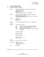
Page 12: ...Gain control Metering Phase meter Left Right by 25 led matrix in a 5 x 5 configuration Acoustic System Three way acoustic system Low Monoaural 1 compression magnet dynamic speaker Mid Stereo 2 compression magnet dynamic speaker High Stereo 2 piezo electric speakers Limiter Incorporated to protect speakers adjusted to the optimal output power Cross over frequencies Low Mid 600 Hz Mid High 4 KHz Fre...

Page 13: ...rmful interference when the equipment is operated in a commercial environment This equipment generates uses and can radiate radio frequency energy and if not installed and used in accordance with the instruction manual may cause harmful interference to radio communications Operation of this equipment in a residential area is likely to cause harmful interference in which case the user will be requi...

Reviews: