BC 2000
DIGITAL
Audio Routing, Mixing and Processing System for Program Production Centers
HARDWARE MANUAL
5
2. BC2000DF / BC2000DF-3. System rack.
General description.
This is the chassis that houses the BC-2000 D system printed circuit boards. It is 4 units high
and 19” deep. The backpanel and the TDM bus terminal board are integrated into the rack, as
well as the system cooling fans (only for BC2000DF chassis).
Composition of the supply.
•
Rack with the relevant boards.
•
4-meter speakon/speakon power supply cable.
•
1-meter flexible, shielded, uncrossed local network cable (for connection through
switch).
Description of the panels.
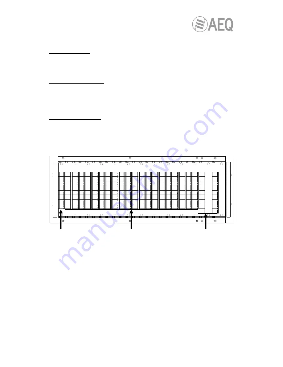
The front section has 21 slots. The first of these (“A“ in the figure below) must be occupied by
a load termination board, and the next 20 slots (“B“) can accommodate up to 20 DSP boards
(BC2221). At the right-hand end of the rack (“C“) a BC2250 front control panel could be placed:
when this front module is mounted in the system, the rack can accommodate up to 18 DSP
boards.
The rear section offers 21 slots (“D“ in the drawing below) to house up to 16 input/output
boards (BC2201, BC2202, BC2203, BC2204, BC2205, BC2206, BC2207, BC2208, BC2209,
BC2210, BC2211, BC2212, BC2312, BC2213, BC2214, BC2224, BC2215, BC2216, BC2217 or
BC2219) and 1 or 2 power supply modules (BC2292). When there are no BC2292 modules in
the system, the rack can accommodate up to 21 input/output boards. There are two slots at the
left end of the chassis (“E“) to house one or two BC2240 controller modules.
A
B
C


