BC 2000
DIGITAL
Audio Routing, Mixing and Processing System for Program Production Centers
HARDWARE MANUAL
62
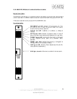
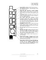
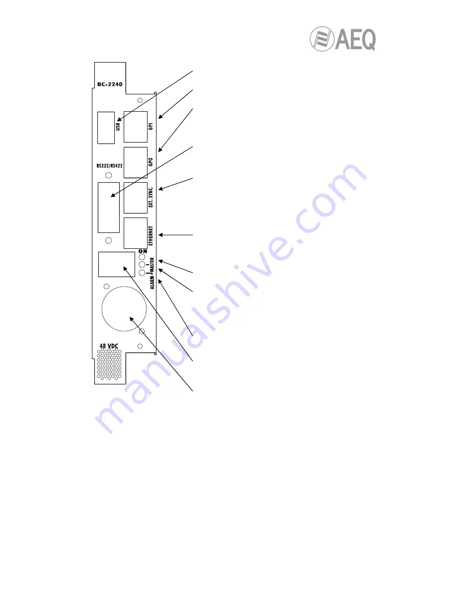
Standard USB connector: host port, A type connector.
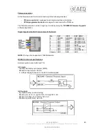
'GPI' RJ45 type connector: 7 general purpose inputs
with a common ground.
'GPO' RJ45 type connector: 7 general purpose
outputs operating through relays, with a common
ground. Suited for control and studio signaling. The
power supply must be external, and the maximum current
is 1A.
'RS232/RS422' DB15 connector: dual connector that
consists of a RS232 auxiliary port, directly connected to
PC, and an “E@sy” RS422 port.
'EXT.
SYNC.'
RJ45
type
connector:
external
synchronism interface able to accept and generate
synchronizing signals in TTL and AES11 formats. While
the AES11 synchronizing output follows the input, the
TTL output has the internal system timing. This board
has a jumper (J11) that can be positioned to load the TTL
synchronizing input with 75 ohms.
'ETHERNET' connector: allows to connect the controller
module through a switch (or directly, by means of a
crossed network cable) to the computer (with the setup
and real time control software).
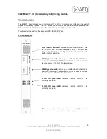
'ON' green LED: indicates the presence of feed power in
the rack.
'MASTER' green LED: indicates whether this card is
operating as the master (LED lighted) or slave unit (LED
off). In normal operation, this LED should be lighted. If
there are two controller boards, the LED will indicate
which of the two is functioning as the master.
'ALARM' red LED: indicates a power supply failure in
any of the boards.
Power-on switch: it turns on the module and the entire
system when a BC2290 or BC2291 external power
supply is used. When a BC2292 power supply module is
used this switch will not be used.
Power supply connector with female SPEAKON type
interlock: allows you to supply power to the module and
the entire rack when a BC2290 or BC2291 external
power supply is used. When a BC2292 power supply
module is used this connector will not be used.

