7
5.5 Collegamenti elettrici aggiuntivi
L’unità necessita della messa a terra.
I collegamenti interni sono eseguiti durante l’assemblaggio in fabbrica.
Per il collegamento tra il CTRL-DSP e la scheda madre utilizzare un cavo twisted-pair, 4 poli, di lunghezza massima 30m.
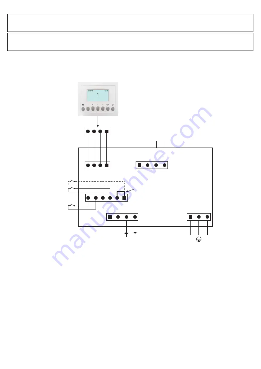
Le immagini successive mostrano lo schema elettrico.
Ingressi/comandi
N°1 connettore alimentazione AC.
N°3 ingressi on/off (contatti puliti), N°1 per sensori ambiente (chiamato IAQ), N°1 per il pulsante Boost (chiamato BST) e N°1
per abilitazione ON/OFF remota (chiamato HY/S1).
N°1 ingresso analogico 1-10V (chiamato SLAVE).
N°1 connettore a 4 poli per CTRL-DSP (RS485 più alimentazione 12Vdc).
Uscite
N°1 uscita on/off per elemento riscaldanete pre o post (contatto a relais - 250Vac 5A).
Fig. 5.g
Collegamenti elettrici sulla scheda madre fissata all’interno della scatola portacontatti
ATTENZIONE
Assicurarsi che l’interruttore generale dell’impianto sia spento prima di qualsiasi operazione di installazione, manutenzione
ordinaria o straordinaria o collegamento elettrico!
ATTENZIONE
L’installazione e la manutenzione dell’unità e del sistema di ventilazione completo deve essere eseguito da un installatore
autorizzato e in conformità alle leggi e ai regolamenti vigenti.
CTRL-DSP
N
L
-
S4
-
+
+
SLA
1-10V
HEAT/CD
+12V
A
B
GND
Ingresso SLAVE
1-10V
Alimentazione AC
Uscita batteria riscaldante
(MAX 250Vac 5A)
Pulsante BOOST (BST)
Ingresso IAQ
(Air Quality e.g. SEN-HY)
Ingresso HY/S1
(per abilitazione
ON/OFF remota)
BST
IAQ
HY/S1
NON RIMUOVERE
(vedere § 7.3 Remote enable)