26
8 MAINTENANCE AND SERVICE
WARNING
Make sure that specific warnings and cautions in Chapter 2 are carefully read, understood and applied!
Maintenance can be carried out by the user.
Service must be performed only by an authorized installer and in accordance with local rules and regulations.
Questions regarding installation, use, maintenance and service of the unit should be answered by your installer or place of
purchase!
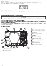
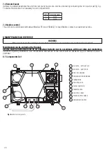
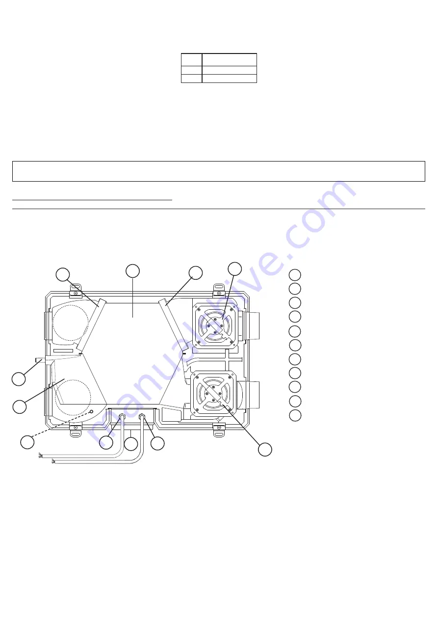
8.1 Components list
1
2
3
4
5
6
7
8
9
G4 FILTER - EXTRACT AIR
G4 FILTER - SUPPLY AIR
HEAT EXCHANGER
CONDENSATION DRAINAGE
THERMISTOR
FAN, INTAKE AIR
FAN, EXHAUST AIR
TERMINAL BOX
CONTROL CABLE
POWER SUPPLY CABLE
CONDENSATION TRAY
10
Fig. 8.a
Internal components
7.2 Remote Enable
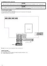
It allows to activate/deactivate the unit from remote by means of a volt-free contact by connecting the In1 input as per fig.5.g.
To enable this function it is necessary to act on dip switch 8.
7.3 Modbus control
The unit can be controlled via Modbus (Modbus RTU over RS485). For specification, contact our customer service.
DIP8
Remote Enable
0
disable
1
enable
M
ANU
TE
NZ
IO
N
E S
TR
AO
RD
INA
RI
A
3
1
2
5
4
6
8
9
7
10
11
11
Summary of Contents for QR120P-W
Page 31: ...31 NOTE ...

