


27
4 TRANSPORT AND STORAGE
The appliance is delivered in one carton box.
The appliance should be stored and transported in such a way that it is protected against physical damage that can harm spigots,
casing, display etc...
It should be covered so that dust, rain and snow cannot enter and damage the unit and its components.
WARNING
Make sure that specific warnings and cautions in Chapter 2 “Precautions” are carefully read, understood and applied!
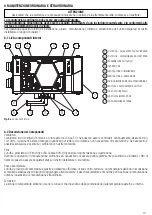
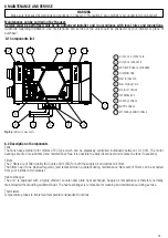
5 INSTALLATION
This section describes how to install the unit correctly.
The unit must be installed according to these instructions.
5.1 Unpacking
Verify that the unit (and eventual accessories) delivered is according to order before starting the installation. Any discrepancies
from the ordered equipment must be reported to the supplier.
5.2 Where/how to install
• All QR units are meant for indoor installation in a heated space.
• The unit must always be mounted horizontally.
• Mount the unit on flat surface (ceiling).
• It’s important that the unit is completely leveled before it is put into operation.
• Place the unit preferably in a separate room (e.g. storage, laundry room or similar).
• When choosing the location it should be kept in mind that the unit requires maintenance regularly and that the inspection door
should be easily accessible.
• Leave free space for opening the removable panel and for removal of the main components (§3.4).
• The outdoor air intake of the building should if possible be put in the northern or eastern side of the building and away from
other exhaust outlets like kitchen fan exhausts or laundry room outlets.
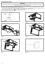
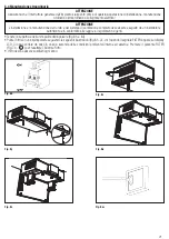
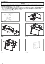
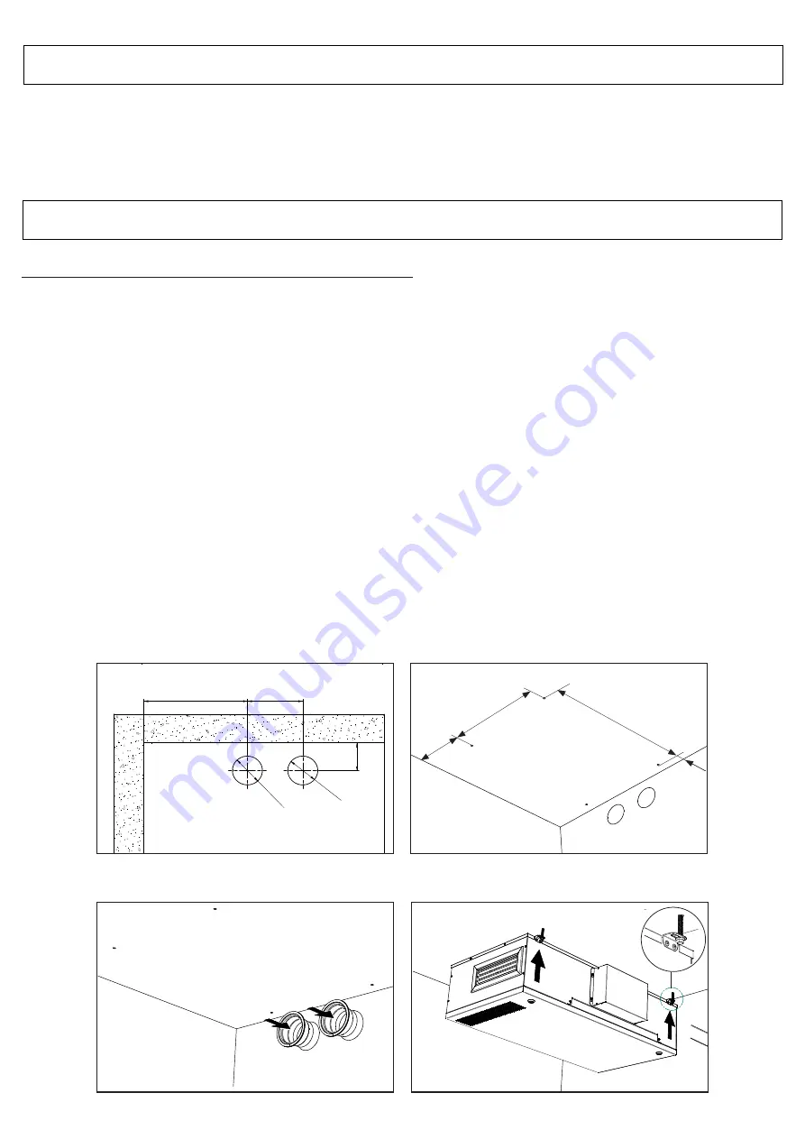
5.3 Ceiling installation
The unit must be installed in the following position.
WARNING
Make sure that specific warnings and cautions in Chapter 2 “Precautions” are carefully read, understood and applied!
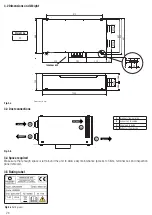
Fig 5.a
Fig. 5.b
1044
420
290
330
53
7
58
4
912
56
5
29
9
28
0
64
1
INSERIRE
VISTA DA SOTTO CON FILTRI
E SCAMBIATORE
TRATTEGGIATI
E SIMBOLI DEI VARI FLUSSI
(COME DA ETICHETTA FLUSSI)
O
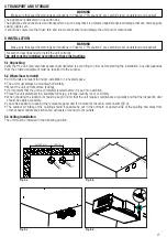
130
mm
O
130
mm
240 mm
450
min.
mm
125
mm
INSERIRE QUOTE DISTANZA FORI
13
0
O
13
0
O
82
125
O
DETAIL A
A
125
15
5
A
DETAIL A
B
DETAIL B
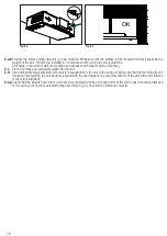
OK!!
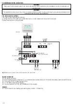
SCHEMI ELETTRICI
MESSA IN SERVIZIO
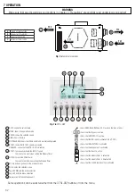
FUNZIONAMENTO
A
DETAIL A
B
DETAIL B
OK!!
SCHEMI ELETTRICI
MESSA IN SERVIZIO
FUNZIONAMENTO
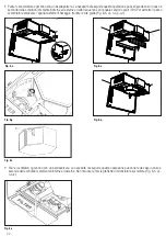
Fig 5.c
Fig. 5.d
1044
420
290
330
53
7
58
4
912
56
5
29
9
28
0
64
1
INSERIRE
VISTA DA SOTTO CON FILTRI
E SCAMBIATORE
TRATTEGGIATI
E SIMBOLI DEI VARI FLUSSI
(COME DA ETICHETTA FLUSSI)
O
130
mm
O
130
mm
240 mm
450
min.
mm
125
mm
INSERIRE QUOTE DISTANZA FORI
13
0
O
13
0
O
82
125
O
DETAIL A
A
125
15
5
288mm
565mm
912mm
67mm
A
DETAIL A
B
DETAIL B
OK!!
SCHEMI ELETTRICI
MESSA IN SERVIZIO
FUNZIONAMENTO
Ø130mm
125 mm
min.450 mm
240 mm
Ø130mm
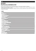
Summary of Contents for QR220DE
Page 47: ...47 NOTE ...


