


6
5.a.b
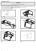
Preparare la superficie sulla quale l’unità deve essere montata. Assicurarsi che essa sia piana, livellata e che sia costruita
in modo da poter sostenere il peso dell’unità. Effettuare l’installazione conformemente a quanto richiesto dalle norme e
regolamenti locali in vigore.
Eseguire i fori nella parete esterna per l’ingresso ed espulsione dell’aria e i fori per il fissaggio a soffitto.
5.c
Fissare alla parete i raccordi per l’ingresso ed espulsione dell’aria.
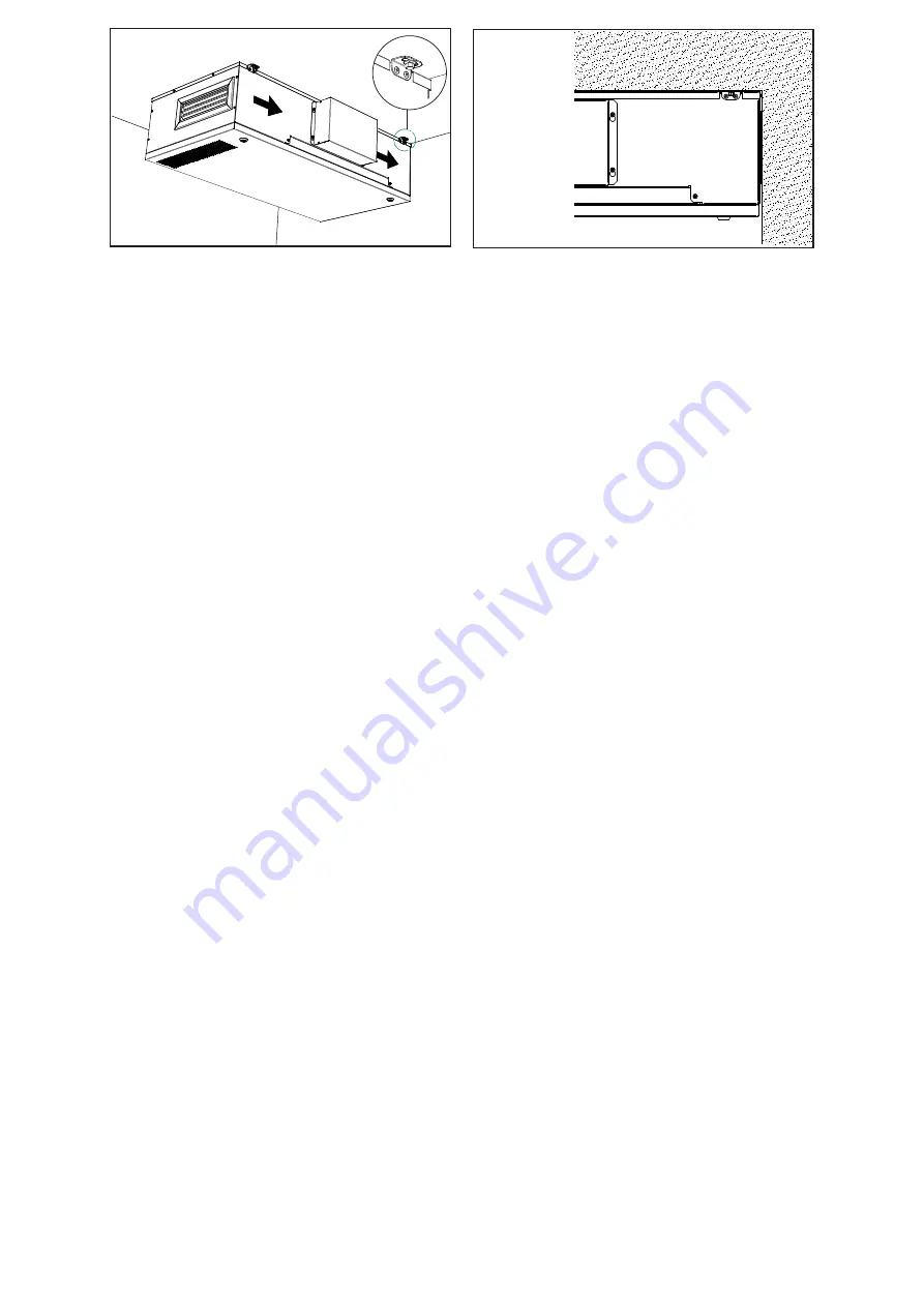
5.d
Utilizzare i tasselli, tiranti o la viteria appropriata (non fornita) per fissare l’unità al soffitto, avendo cura che i due fori per
l’ingresso ed espulsione dell’aria (da e verso l’esterno) sul corpo dell’unità siano allineati con i raccordi fissati alla parete .
Si raccomanda di montare l’unità utilizzando dei giunti antivibranti (non forniti).
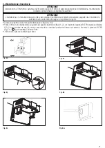
5.e.g
Assicurasi che i raccordi fissati alla parete siano ben agganciati alla macchina e che il corpo principale sia ben fissato al
soffitto. Collegare elettricamente l’unità come indicato nel punto 5.4. Verificare che si attivi correttamente.
A
DETAIL A
B
DETAIL B
OK!!
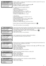
SCHEMI ELETTRICI
MESSA IN SERVIZIO
FUNZIONAMENTO
A
DETAIL A
B
DETAIL B
OK!!
SCHEMI ELETTRICI
MESSA IN SERVIZIO
FUNZIONAMENTO
Fig. 5.e
Fig. 5.f
A
DETAIL A
B
DETAIL B
OK!!
SCHEMI ELETTRICI
MESSA IN SERVIZIO
FUNZIONAMENTO
Summary of Contents for QR220DE
Page 47: ...47 NOTE ...


