


It allows to select one language among English, Italiano, Deutsch,
Č
eština, Slovenský, Français,
Español, Nederlandse,
中国
, Magyar and
Русский
.
Press OK to enter.
Select the language using
or
.
Press OK to select.
Factory setting (DEFAULT): English.
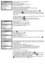
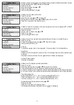
Installer Menu
1 Language
2 Date/time
3 Machine orientation
4 Normal Mode
6 Bypass settings
It allows to set the date and the time.
Press OK to enter.
Select the item using
or
and press OK.
Set the date and the time using
or
and press OK to confirm.
Press ESC to go back to the previous menu.
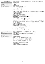
Installer Menu
1 Language
2 Date/time
3 Machine orientation
4 Normal Mode
6 Bypass settings
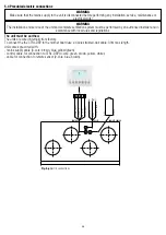
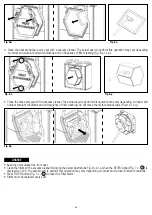
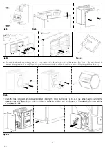
It allows to select the orientation of the duct connections from and to outside (LEFT or RIGHT
hand configuration as per § 3.3).
Press OK to enter.
Choose “Left” or “Right” using
or
.
Press OK to select.
Factory setting (DEFAULT): Left.
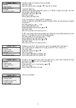
Installer Menu
1 Language
2 Date/time
3 Machine orientation
4 Normal Mode
6 Bypass settings
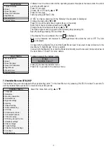
It allows to select one operation among Normal Mode 3V, Slave or Constant Pressure.
Press OK to enter.
Choose the operation mode using
or
. Press OK to select.
Factory setting (DEFAULT): 3V
3V Mode
To adjust the speeds, refer to the paragraph “10 Speed setting” in the Installer Menu.
Slave Mode
It allows to control the speed by means of the 0-10V analogic input: any other operation logic
is ignored.
If the Slave mode is activated, the icon and the word Slave are displayed.
Constant Pressure Mode
Currently not available.
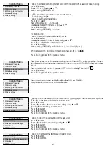
Installer Menu
1 Language
2 Date/time
3 Machine orientation
4 Normal Mode
6 Bypass settings
It allows to set the Bypass operation parameters.
Press OK to enter.
Select the submenu item using
or
and press OK to confirm:
1 Desired Temperature: it is the ambient temperature desired by the user.
2 Tmax Free Heating: it is the maximum allowed outside temperature for free heating operation.
3 Tmin Free Cooling: it is the minimum allowed outside temperature for free cooling operation.
The setting ranges are:
Desired Temperature: 15°C ÷ 30°C. Factory setting (DEFAULT): 23°C.
Tmax Free Heating: 25°C ÷ 30°C. Factory setting (DEFAULT): 28°C.
Tmin Free Cooling: 15°C ÷ 20°C. Factory setting (DEFAULT): 18°C.
Increase/decrease the temperature using
or
.
Press OK to select.
Press ESC to go back to the previous menu.
If the Bypass functionality is activated, the icon is displayed.
Installer Menu
1 Language
2 Date/time
3 Machine orientation
4 Normal Mode
6 Bypass settings
18


