16
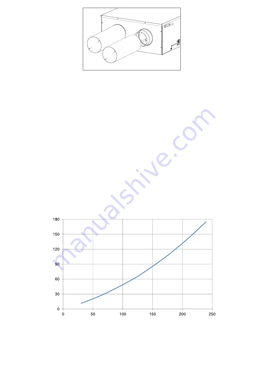
Fig. 5.e
5.a
Prepare the surface where the unit is to be mounted. Make sure that the surface is flat, leveled and that it supports the weight
of the unit. Perform the installation in accordance with local rules and regulations.
5.b
Use appropriate plugs and rods or screws (not supplied) to fix the unit to the ceiling. It is recommended to fit the unit with
anti-vibration mounts (not supplied).
5.c
Assure that the unit is completely flat once mounted to the ceiling, for the condensation drainage to function properly.
5.d
Connect the condensation elbow(s) to the drainage hole(s) on the access panel: in case close and seal the non-used hole
with the supplied plugs (2 plugs each hole). Make sure of water and air tightness of all connections. The condensation pipe
connection must be done in a way that makes easy to remove the access panel for the service operation. It is recommended
to use a U-bend (or similar) in the condensation drainage pipe.
5.e
Connect the unit to the duct system. Make sure that all necessary accessories are used to create a functional ventilation
solution.
Ø125
Ø125
6 COMMISSIONING
6.1 Pressure drop and efficiency
Figure 6. a
represents the pressure drop curve of the passive module
Figure 6. b
represents the efficiency curve of the heat exchanger pack (thermal efficiency according to EN308)
Table 6. c
shows the efficiency of the heat exchanger pack and the condensation amount produced in different climatic con-
ditions, to help the decision of the system designer or installer to connect one or both condensate drains. High condensation
production is a direct consequence of high efficiency and humidity.
Static Pressure - Pa
Airflow - m
3
/h
Fig. 6.a
Summary of Contents for QRP125
Page 22: ...22 NOTE ...
Page 23: ...23 NOTE ...


