


Condensate Neutralization Tank User Instructions
TID-0074_0H
•
8/22/2022 Technical Support
•
(800) 526-0288
•
Mon-Fri, 8 am - 5 pm EST Page
12
of
14
mA OUT
RS-485
COMM.
+
-
+
-
ANALOG IN
SENSOR COMMON
OUTDOOR SENSOR IN
REMOTE INTL'K IN
B.M.S. (PWM) IN
SHIELD
+
-
+
-
(AIR) AUX SENSOR IN
NOT USED
EXHAUST SWITCH IN
DELAYED INTL'K IN
FAULT RELAY
120 VAC, 5A, RES
AUX RELAY
120 VAC, 5A, RES
G
RELAY CONTACTS:
120 VAC, 30 VDC
5 AMPS RESISTIVE
DANGER
120 VAC USED
IN THIS BOX
NOT USED
NOT USED
NC
COM
NO
NC
COM
NO
NOT USED
0
– 10V
AGND
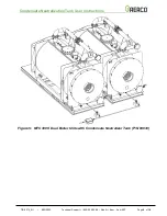
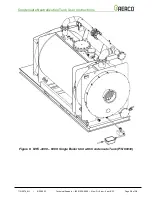
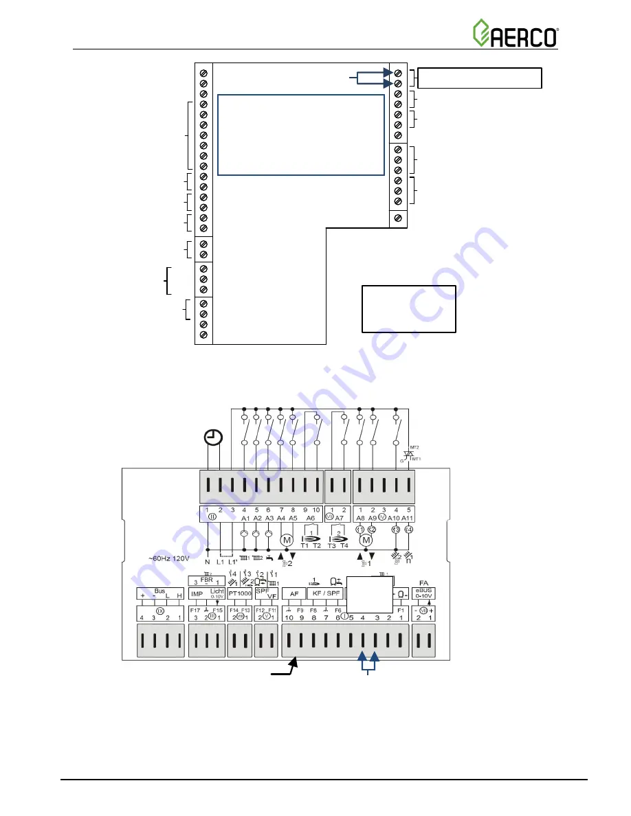
Figure 8: BMK, KC, and INN I/O Box Wiring for Overflow Switch Relay Connection
(REMOTE
INTL’K IN)
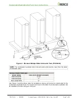
Figure 9: Modulex E8 Controller Wiring for Overflow Switch Relay Connection
(Pins 3 & 4 of Connector I)
Pins
4 - 3
Overflow Switch
Relay Connections
Modulex Connector I
NOTE:
Remove the jumper between
the two
“REMOTE INTL”K IN”
terminals before connecting
the Overflow Switch Relay.
Overflow Switch
Relay Connections
REMOTE INTL’K IN


