background image

Condensate Neutralization Tank User Instructions 


TID-0074_0H

      •

      8/22/2022                  Technical Support  

  (800) 526-0288  

  Mon-Fri, 8 am - 5 pm EST                   Page 

4

  of 

14


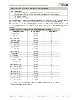
TABLE 3: Neutralizer Tank Application Chart (MFC Series)


AERCO Equipment 

BTU/Hr. Input 

Kit Qty Required 

Two (2) MFC 3000 

6,000,000 

One (1) MFC 4000 

4,000,000 

One (1) MFC 5000 

5,000,000 

One (1) MFC 6000 

6,000,000 

One (1) MFC 8000 

8,000,000 

2** 

One (1) MFC 10000 

10,000,000 

2** 

** Neutralizer tanks are to be installed in parallel.  Do not install multiple neutralizer tanks in series. 


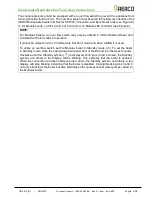
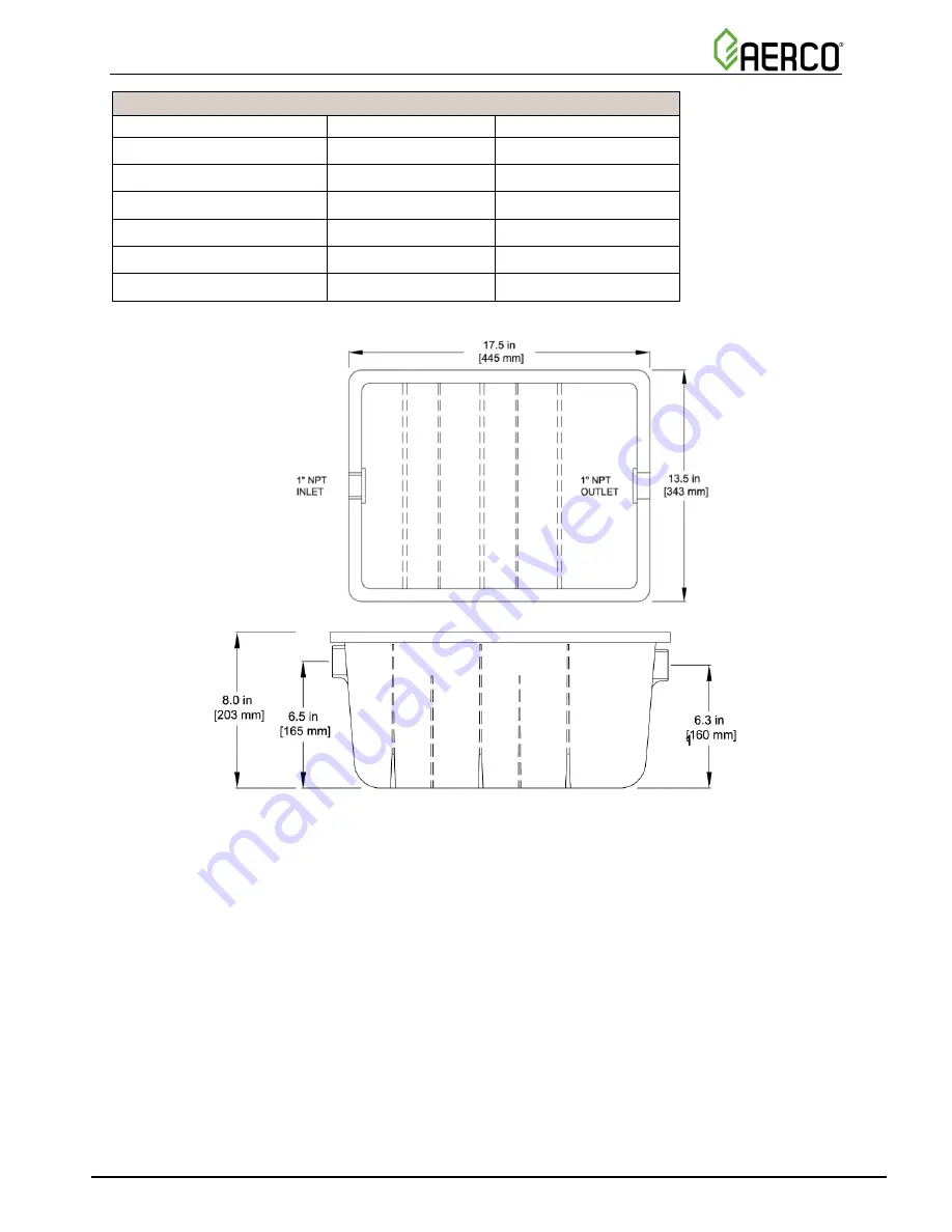
Figure 1:  Condensate Neutralization Tank (P/N 89030) Dimensions 

The inlet connection (6.5") is higher than the outlet connection (6.3"). Set the neutralization tank 
on a secure and level base. Connections to the appliance and neutralization kit must be installed 
to ensure that no condensate backflow can occur. Connect appliance  condensate drain to the 
inlet using corrosion resistant piping. Do not route the condensate line through any area that is 
exposed  to  freezing  temperatures.  If  traffic  poses  a  risk,  install  some  protection  to  prevent 
movement  and/or  damage.  Mount  as  per  installation  diagram.  Ensure  that  no  air  pockets  will 
remain or form in the piping and that the condensate will flow freely from the appliance condensate 
drain  into  the  tank  and  then  to  the  drain.  Access  to  the  discharge  is  necessary  for  proper 
maintenance in order to check the effectiveness of the neutralizing media, using pH test strips.  

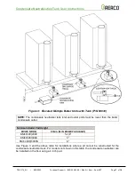
If there is no gravity drain available or if the boiler/water heater cannot be elevated to be higher 
than the Neutralization Tank, install a condensate removal pump designed for use on condensing 
boilers and furnaces (Figure 4).   


Summary of Contents for 89030

Page 1: ...m Gas Burning Boilers Water Heaters Technical Instruction Document Applies to the following AERCO models Benchmark Series Innovation Series Recon Series MFC Series natural gas only Modulex Series AM Series Maintenance only For tank installation see O M manual GF 146 KC1000 Models TID 0074_0H 8 22 2022 Disclaimer The information contained in this manual is subject to change without notice from AERC...

Page 2: ...ON INSTRUCTIONS NOTE Check with your local water authority for regulations regarding discharge of treated condensate into a drain or sewer system WARNING RISK OF DAMAGE TO APPLIANCE Follow these instructions carefully to avoid damage to equipment and appliances The Condensate Neutralization Tank can be installed using either of the following methods Neutralization tank is installed such that the i...

Page 3: ...2 and 3 for selection guideline for all AERCO gas fired products TABLE 2 Neutralizer Tank Application Chart BMK INN MLX EXT AERCO Equipment BTU Hr Input Kit Qty Required Eight 8 BMK750 6 000 000 1 Six 6 BMK1000 6 000 000 1 Four 4 BMK1500 6 000 000 1 Three 3 BMK2000 6 000 000 1 Two 2 BMK2500 5 000 000 1 Four 4 BMK2500 10 000 000 2 Two 2 BMK3000 6 000 000 1 Four 4 BMK3000 12 000 000 2 One 1 BMK6000 ...

Page 4: ...nd neutralization kit must be installed to ensure that no condensate backflow can occur Connect appliance condensate drain to the inlet using corrosion resistant piping Do not route the condensate line through any area that is exposed to freezing temperatures If traffic poses a risk install some protection to prevent movement and or damage Mount as per installation diagram Ensure that no air pocke...

Page 5: ...or Reset and Constant Set Point modes of operation It cannot be utilized in 0 to 10 Volt Remote Set Point mode and when a BMS II is used To utilize an overflow switch set the Modulex boiler to Standby mode To set the boiler to Standby mode close the swing down front panel door of the E8 and turn the wheel counter clockwise until the Standby symbol is displayed With pins 3 and 4 closed the Standby ...

Page 6: ...th Tank P N 89030 Placed in a Pit Minimum Pit Depth BOILER MODEL DIM A MIN PIT DEPTH BMK1500 2000 1 1 4 BMK2500 3000 1 BMK 4000 5000N 2 Use Figure 2 and the above table for installations where a boiler pad no thicker than 4 is desired For models not shown in this table the condensate neutralizer can be installed on the floor while the boiler is installed on a 4 inch pad ...

Page 7: ...er tank inlet and outlet ports must be lower than the boiler condensate outlet Minimum Boiler Pad Height BOILER MODEL DIM A MIN BOILER PAD HEIGHT BMK1500 2000 5 1 4 BMK2500 3000 5 BMK 4000 5000N 6 Use Figure 3 and the above table for installations where a pit cannot be constructed for the condensate neutralizer tank For models not shown in this table the condensate neutralizer can be installed on ...

Page 8: ...densate Neutralization Tank User Instructions TID 0074_0H 8 22 2022 Technical Support 800 526 0288 Mon Fri 8 am 5 pm EST Page 8 of 14 Figure 4 Multiple Boiler Units with Tank and Condensate Pump P N 89030 ...

Page 9: ...ate Neutralization Tank User Instructions TID 0074_0H 8 22 2022 Technical Support 800 526 0288 Mon Fri 8 am 5 pm EST Page 9 of 14 Figure 5 MFC 3000 Dual Boiler Units with Condensate Neutralizer Tank P N 89030 ...

Page 10: ...ensate Neutralization Tank User Instructions TID 0074_0H 8 22 2022 Technical Support 800 526 0288 Mon Fri 8 am 5 pm EST Page 10 of 14 Figure 6 MFC 4000 6000 Single Boiler Unit with Condensate Tank P N 89030 ...

Page 11: ...ate Neutralization Tank User Instructions TID 0074_0H 8 22 2022 Technical Support 800 526 0288 Mon Fri 8 am 5 pm EST Page 11 of 14 Figure 7 MFC8000 10000 Single Boiler Unit with Two Condensate Tanks P N 89030 ...

Page 12: ... RELAY CONTACTS 120 VAC 30 VDC 5 AMPS RESISTIVE DANGER 120 VAC USED IN THIS BOX NOT USED NOT USED NC COM NO NC COM NO NOT USED 0 10V AGND Figure 8 BMK KC and INN I O Box Wiring for Overflow Switch Relay Connection REMOTE INTL K IN Figure 9 Modulex E8 Controller Wiring for Overflow Switch Relay Connection Pins 3 4 of Connector I Pins 4 3 Overflow Switch Relay Connections Modulex Connector I NOTE Re...

Page 13: ...readings obtained compared to local water authority requirements The neutralizing media should be replaced when the pH level drops below the minimum level of the local water authority For replacement media contact your local AERCO sales representative Replacement neutralization media for KC BMK INN Recon MFC and Modulex series models is P N 89031 Replacement neutralization media for AM Series mode...

Page 14: ...chnical Support 800 526 0288 Mon Fri 8 am 5 pm EST Page 14 of 14 Change Log Date Description Changed By 11 13 2019 Rev F DIR 19 71 Updated overall format Updated Figure 3 Linley Thobourne 8 22 2022 Rev G Added BMK 4000 5000N to tables Lisa Weiss AERCO International Inc 2022 ...

Reviews: