SAFETY DEVICE TESTING
6-6
5. The unit should begin it’s start sequence,
then shut down and display
PRG SWITCH
OPEN DURING PURGE.
17
2
17
1
16
9
17
0
6. Replace the wire on the Purge Switch and
depress
the CLEAR
button. The unit should
restart.
6.11 IGNITION SWITCH OPEN DURING
IGNITION
The Ignition Switch (and the Purge Switch) is
located on the Air/Fuel Valve. To check the
switch, proceed as follows:
1. Set the unit’s
ON/OFF
switch to the
OFF
position.
2. Place the unit in Manual Mode and set the
valve position between 25% and 30%.
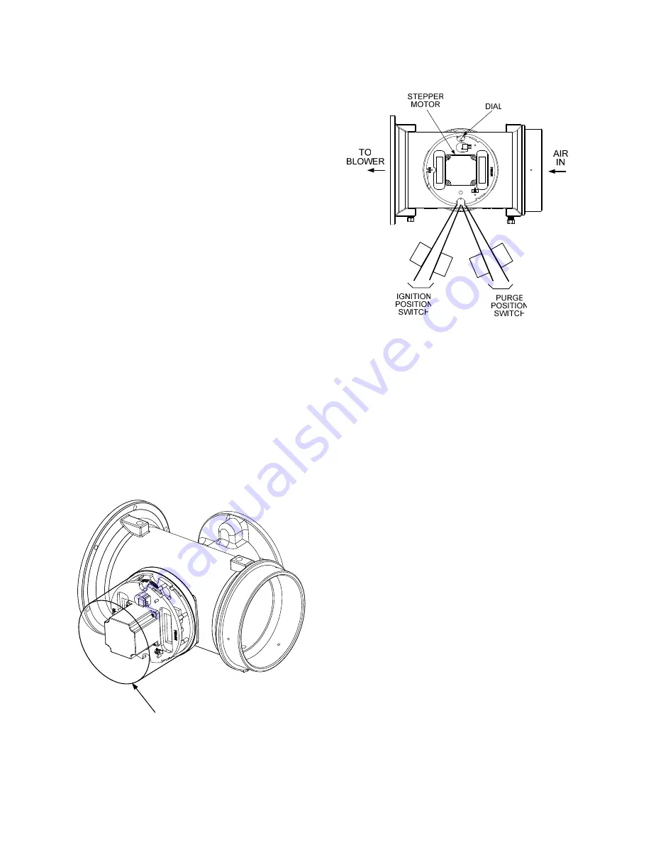
3. Remove the Air/Fuel Valve cover (Figure
6-5) by rotating the cover counterclockwise
to unlock and lift up to remove.
Figure 6-6
Air/Fuel Valve Purge and Ignition Switch
Locations
4. Remove one of the two wires (#169 or #170)
from the Ignition Switch (Figure 6-6).
5. Initiate a unit start sequence.
6. The unit should begin it’s start sequence
and then shut down and display
IGN
SWITCH OPEN DURING IGNITION.
6.12 SAFETY PRESSURE RELIEF
VALVE TEST
Test the safety Pressure Relief Valve in
accordance with ASME Boiler and Pressure
Vessel Code, Section VI.
7. Replace the wire on the Ignition Switch and
press the
CLEAR
button. The unit should
restart.
AIR/FUEL VALVE COVER
(ROTATE CCW TO REMOVE)
Figure 6-5
Air/Fuel Valve Cover Location
Summary of Contents for Benchmark 2.0
Page 4: ......
Page 8: ......
Page 12: ......
Page 24: ......
Page 44: ......
Page 50: ......
Page 78: ......
Page 84: ......
Page 88: ......
Page 90: ......
Page 101: ...APPENDIX F F 5 ...
Page 102: ...APPENDIX F F 6 ...
Page 104: ...APPENDIX F F 8 ...
Page 105: ...APPENDIX F F 9 ...
Page 106: ...APPENDIX F F 10 ...
Page 107: ...APPENDIX F F 11 ...
Page 108: ...APPENDIX F F 12 ...
Page 112: ...APPENDIX G G 4 ...
Page 113: ...APPENDIX H H 1 ...
Page 114: ...APPENDIX H H 2 ...
Page 115: ...APPENDIX H H 3 ...
Page 118: ......
Page 119: ...APPENDIX J BENCHMARK CONTROL PANEL EXPLODED VIEW J 1 ...
Page 120: ...APPENDIX J J 2 P1 P2 P3 P4 P5 P6 BENCHMARK CONTROL PANEL REAR VIEW ...
Page 122: ......


