MAINTENANCE
To inspect or replace the burner assembly:
1. Set
the
ON/OFF
switch on the control panel,
to the
OFF
position. Disconnect AC power
from the unit and turn off the gas supply.
2. Remove the side and top panels from the
unit to provide access to the burner
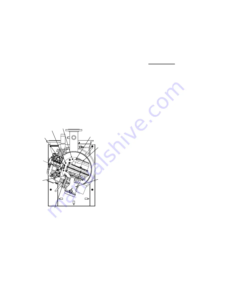
assembly. See Figure 7-4.
3. Disconnect the lead wire from the flame
detector installed on the burner plate (Figure
7-4).
4. Remove the two (2) screws securing the
flame detector to the plate. The flame
detector is secured to the burner plate with
one (1) #10-32 screw and one (1) #8-32
screw.
5. Remove the flame detector and gasket from
the burner plate.
6. Disconnect the cable from the ignitor-
injector.
IGNITOR-
INJECTOR
3/8-16
NUTS (8)
BLOWER
BURNER
PLATE
AIR/FUEL
VALVE
FLAME
DETECTOR
STAGED
IGNITION
ASSEMBLY
1/2” BOLTS & NUTS (4)
CONNECT AIR/FUEL VALVE
TO GAS TRAIN
GROUNDING
SCREW
(10-32 x 1/2" LG.)
Figure 7-4
Burner Disassembly Diagram
7. Using a 7/16” open-end wrench, disconnect
the compression nut securing the gas
injector tube of the ignitor-injector to the
elbow of the staged ignition assembly (see
Figure 7-2). Disconnect the staged ignition
assembly from the ignitor-injector.
IMPORTANT
Prior to removing the ignitor-injector,
note the position of the gas injector
tube relative to the burner plate and
blower. This is necessary to ensure
that the ignitor injector is reinstalled in
the proper orientation when it is
reconnected to the staged ignition
assembly.
8. Next, loosen and remove the ignitor-injector
from the burner plate using a 1" open-end
wrench.
9. Disconnect the unit wiring harness
connectors from the air/fuel valve and
blower motor.
10. Disconnect the wire leads connected to the
blower proof switch and blocked inlet switch
(Figure 7-5).
11. Remove the 10-32 x 1/2" long grounding
screw from the burner plate. Refer to Figure
7-4.
12. Disconnect the gas train from the air/fuel
valve flange by removing the four 1/2” bolts
and nuts (Figure 7-4).
13. Disconnect the inlet air flex hose from the
air/fuel valve by loosening the hose clamp.
14. Remove the six (6) 1/4-20 hex nuts and flat
washers securing the blower to the burner
plate (Figure 7-5).
7-4
Summary of Contents for Benchmark 2.0
Page 4: ......
Page 8: ......
Page 12: ......
Page 24: ......
Page 44: ......
Page 50: ......
Page 78: ......
Page 84: ......
Page 88: ......
Page 90: ......
Page 101: ...APPENDIX F F 5 ...
Page 102: ...APPENDIX F F 6 ...
Page 104: ...APPENDIX F F 8 ...
Page 105: ...APPENDIX F F 9 ...
Page 106: ...APPENDIX F F 10 ...
Page 107: ...APPENDIX F F 11 ...
Page 108: ...APPENDIX F F 12 ...
Page 112: ...APPENDIX G G 4 ...
Page 113: ...APPENDIX H H 1 ...
Page 114: ...APPENDIX H H 2 ...
Page 115: ...APPENDIX H H 3 ...
Page 118: ......
Page 119: ...APPENDIX J BENCHMARK CONTROL PANEL EXPLODED VIEW J 1 ...
Page 120: ...APPENDIX J J 2 P1 P2 P3 P4 P5 P6 BENCHMARK CONTROL PANEL REAR VIEW ...
Page 122: ......


