Aercus Instruments™
- WeatherSleuth®
17 |
P a g e
3.6.3 WeatherSleuth® Connections
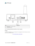
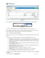
Connect the WeatherSleuth® receiver power jack to AC power with the power adapter (included), as
shown in Figure 15, reference 10.
Connect the WeatherSleuth® receiver to your router using the Ethernet cable (included), as shown in
Figure 15, reference 8.
Place the sensor array and indoor thermo-hygrometer transmitter about 1.5 to 3m from the
WeatherSleuth® receiver and wait several minutes for the remote sensors to synchronise with the
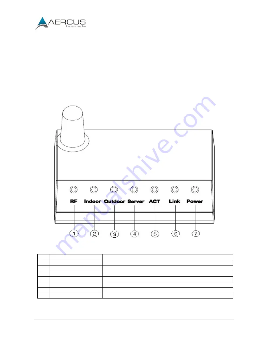
receiver. Once synchronised, the Indoor blue LED (Figure 14, reference 2) and Outdoor blue LED
(Figure 14, reference 3) will be illuminated.
Figure 14
Ref
LED
Description
1
RF
On when radio frequency receiver is operating properly
2
Indoor
On when indoor sensor received
3
Outdoor
On when outdoor sensor array received
4
Server
On when connected to Wunderground.com internet hosting service
5
ACT
Flashes when there is internet activity
6
Link
Connected to the Internet (or router)
7
Power
AC Power connected
Summary of Contents for WeatherSleuth
Page 1: ...v1 2 WeatherSleuth PROFESSIONAL IP WEATHER STATION WITH DIRECT REAL TIME INTERNET PUBLISHING ...
Page 11: ...Aercus Instruments WeatherSleuth 11 P a g e Figure 6 ...
Page 36: ...Aercus Instruments WeatherSleuth 36 P a g e Figure 30e ...
Page 39: ...Aercus Instruments WeatherSleuth 39 P a g e Figure 32 Figure 33 ...
Page 54: ...Aercus Instruments WeatherSleuth 54 P a g e Figure 6 ...
Page 80: ...Aercus Instruments WeatherSleuth 80 P a g e Figure 30e ...
Page 83: ...Aercus Instruments WeatherSleuth 83 P a g e Figure 32 Figure 33 ...

