17/22
TF5774_C
Aereco S.A.
3)
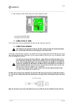
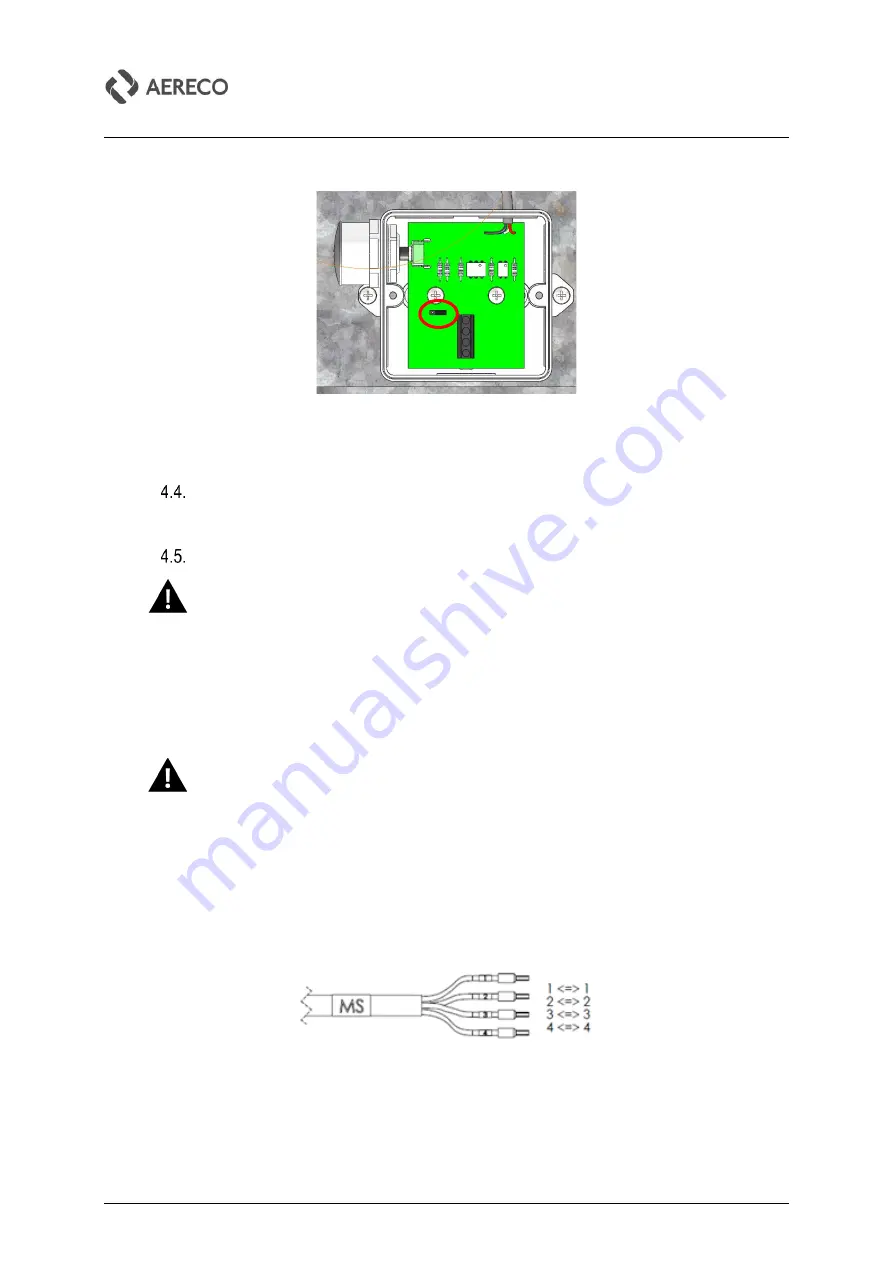
Place the jumper at bottom left according to the chosen management mode:
▪
on pins 1 & 2 for the "MS" mode
▪
on pins 2 & 3 for the “ST” mode
CONNECTION IN ST MODE
The ST mode
doesn’t
require any additional specific connection other than power connection.
CONNECTION IN MS MODE
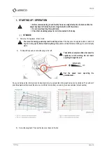
Check that the power supply has in fact been cut off for at least 5 minutes before starting (to eliminate
the risk of electrical shocks from the discharging of certain components).
In this mode, each fan has its own control line. The operation consists in connecting the cable from the MS device to the control
cable of the management module (FAN module). For the complete installation of the MS mode, refer to the installation manual
of the MS management components.
The cable must be between Ø6 mm and Ø12 mm, comply with the installation standards in force,
have 4 conductors each having a cross section of at least 1.5 mm², be no longer than 25 m between
the fan and its management module, and be able to withstand the installation environment (in
particular, be resistant to UV). Depending on the EMC specific to the installation site, the cable must
be put in a metallic shield.
These recommendations ensure the EMC and limit the tension lost. Above this
length, the good working of t
he appliance won’t be guaranteed.
The cable must not include a yellow & green conductor, the colour pair used only for earth wires.
The current in these cables does not exceed 20 mA.
The
“MS”
cable of the fan can be identified by the annotation “MS” at its edge. Each wire
is marked with a number: 1,
2, 3, 4. Connect the cable and mark each wire (using colours for example) in order to identify which wire is connected:
1, 2, 3, 4.
MS cable edge
Make the connection in accordance with standard practice via an IP65 junction box installed at the base of the fan.


