21/36
Aereco S.A.
2)
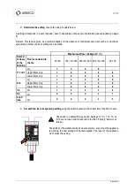
Determine the setting
of each fan using the table below.
A setting corresponds to a set of speeds (“Level”), depending on the sensor information (see explanation on page
6).
Remark: This table is given as a recommendation. In the absence of contractual document such as a technical
agreement, another choice of settings can be made.
Maximum a leakage (m
3
/ h)
Number
of floors
of the
building
Floors connected to
the fan
Q<150
150 <Q< 300 300 <Q< 500 500 <Q< 700
Q> 700
11 and +
All
1
3
6
8
-
Upper floors only
1
2
4
4
8
Lower floors only
1
2
9
9
9
9-10
All
1
3
6
8
9
Upper floors only
1
2
3
3
8
Lower floors only
1
2
9
9
9
7-8
All
1
3
4
7
8
5-6
All
2
3
3
3
7
4 and
less
All
2
2
2
3
5
3)
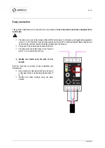
Set each fan its corresponding setting
using the switch located on the bottom left of the Fan module.
The switch is a default 16-way switch. Settings 0, 10, 11, 12, 13, 14
& 15 are not used and correspond to the fan off (See §
“Defects and
failures”)
The setting of the module can be done at every time, even when the appliance
is working, the new setting will be then applied. The reset of the appliance
won’t erase this setting.
Summary of Contents for VBP+
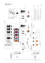
Page 11: ...11 36 Aereco S A ...
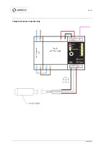
Page 13: ...13 36 Aereco S A Temperature sensor connection only ...
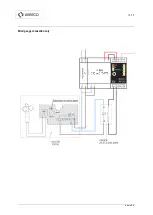
Page 14: ...14 36 Aereco S A Wind gauge connection only ...
Page 15: ...15 36 Aereco S A Clock connection only ...
Page 16: ...16 36 Aereco S A Temperature sensor wind gauge connection ...
Page 17: ...17 36 Aereco S A Temperature sensor clock connection ...
Page 35: ...35 36 Aereco S A ...

