6/36
Aereco S.A.
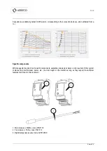
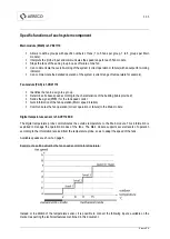
Specific functions of each system component
Main module (MAIN) ref. VB21119
Allows to define groups with specific numbers of fans (1 to 5 fans per group, 1 to 5 groups per Main
module).
Interprets the 'probe' input and communicates the speed range for each Fan module.
Stops the fans of the same group in case of failure of one fan.
Can communicate the overall working of the system (correct operation or failure) with an output for working
indicator.
Can communicate the detailed operation of the system (current range of temperature for example).
Fan module (FAN) ref. VB21118
Identifies the fan to assign to a group
Determines its base speed according to the characteristics of the building (table provided)
Sends the signal (PWM ) for the fan speed control
Gets information of the fan operation (Motor speed rotation)
Communicates the fan operation (correct operation or failure) to the Main module
Digital temperature sensor ref. AVE1146XX
The digital temperature probe communicates the outside temperature to the Main module. This information is
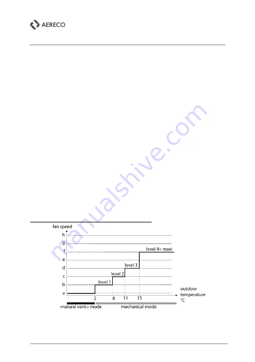
exploited to manage the operation modes of the fans. The Main module supports several levels of operation
according to the information received from the temperature probe, so as to adapt the speed of the fans.
Available speeds are shown on page 5.
Example of a setting adjusting the fan speed according to temperature:
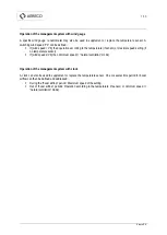
Instead or in addition of the temperature sensor, it is possible to connect the following inputs, available on the
market, respecting the technical features mentioned in this document.
Summary of Contents for VBP+
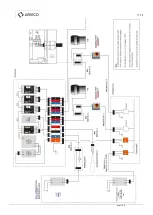
Page 11: ...11 36 Aereco S A ...
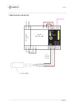
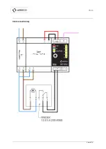
Page 13: ...13 36 Aereco S A Temperature sensor connection only ...
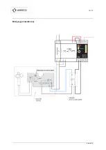
Page 14: ...14 36 Aereco S A Wind gauge connection only ...
Page 15: ...15 36 Aereco S A Clock connection only ...
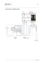
Page 16: ...16 36 Aereco S A Temperature sensor wind gauge connection ...
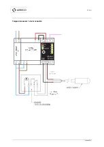
Page 17: ...17 36 Aereco S A Temperature sensor clock connection ...
Page 35: ...35 36 Aereco S A ...


