background image


33/36 


Aereco S.A. 


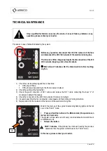
TECHNICAL MAINTENANCE 


Only a qualified technician can access the device. In case of failure, problems or any 

questions, please contact your reseller.  


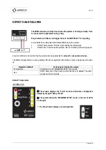
Procedure in case of default indicated by the system: 


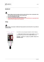
Before any operation, disconnect the 230 VAC network of the fans 

and disconnect the 230 VAC network of the electronic driving box.  


The fans can still be charged up despite the disconnection of the 230 

VAC network, implying a risk of electric shock. 
 

 Wait at least 5 minutes after the disconnection before touching 

any fan. 


1)


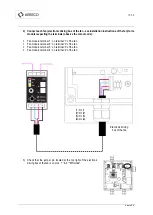
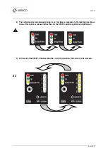
Check the electrical drawing and the connections: 


Of the input ‘Probe’. 


Of the fan(s) corresponding to the Fan modules in default. 

2)


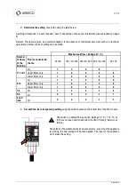
Check the setting of the faulted fan  

3)


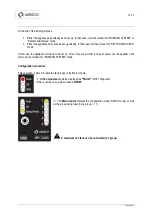
Check  the  good  connection  of  RJ11  cables  and  replace  the  RJ11  cable  connecting  the  input  “L"  of 

module(s) in default if necessary. 

4)


Check the connection of the 230 VAC network of the fan(s) in default. 

5)


Visually inspect that the fan in default is not damaged and that nothing is forcing its turbine.  

6)


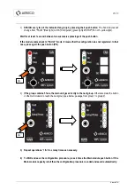
Replace the 230 VAC network of the fan and of the electronic driving box.  


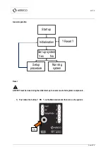
Wait for the start-up of the system (descending flashing light) and the fail 

over in the 'FAULT’ mode. 


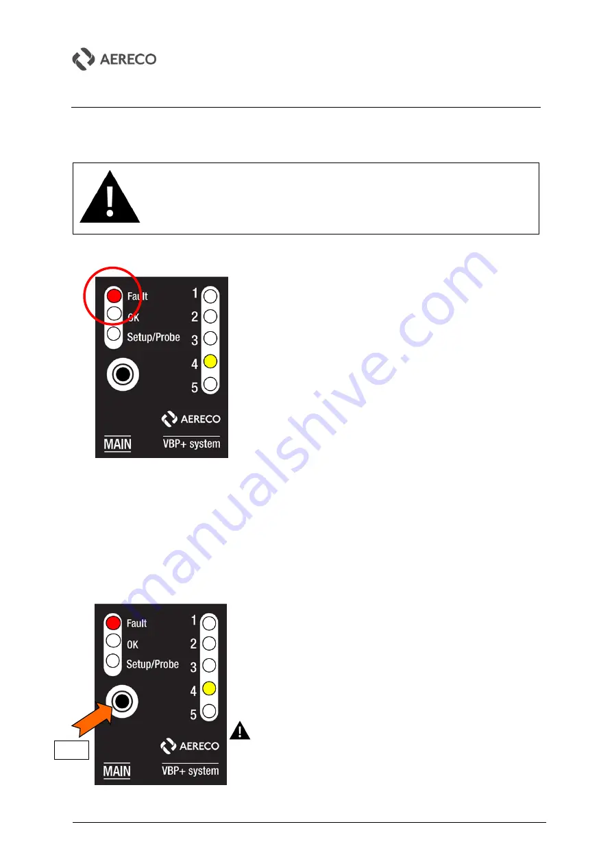
Press and hold the button on the Main module (the operation can 

last up to 20 seconds). 

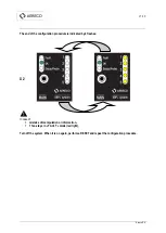
The system will operate a reset of every recorded default and switch back 

to NORMAL mode. 


Release the button. 


WAIT 5 minutes

. If the problem has not been fixed by the previous 

operations then the system will fall back to the FAULT mode.  


In this case, please contact your reseller. 


PB 

Summary of Contents for VBP+

Page 1: ...1 36 TF5602_E Aereco S A Installation and maintenance Download this document on www aereco com MS Management System VBP ENGLISH ...

Page 2: ... INSTALLATION ELECTRICAL CONNECTIONS 10 GENERAL ELECTRICAL CONNECTIONS 10 SENSOR S ELECTRICAL CONNECTIONS 12 Temperature sensor connection only 13 Wind gauge connection only 14 Clock connection only 15 Temperature sensor wind gauge connection 16 Temperature sensor clock connection 17 FAN S CONNECTION 18 START UP 20 SETTING 20 General operation 22 Reset 22 Initialisation 24 Configuration procedure ...

Page 3: ... appliance with wet or damp body hands feet even if it is connected to the ground This appliance is not intended for use by persons including children with reduced physical sensory or mental capabilities or lack of experience and knowledge unless they have been given supervision or instruction concerning use of the appliance by a person responsible for their safety To avoid any risk do not allow t...

Page 4: ... possibility of wind gauge or clock These components can be placed in an IP65 electric box if outside not included and clipped on DIN rail They are interconnected through RJ11 wires supplied of about 25 cm1 The connection of Fan modules to the fans is realised by the mean of four wires standard cable Functions of MS management system Manages the simultaneous operation of inter connected fans Manag...

Page 5: ...anagement system has 3 specific components available exclusively at Aereco or its resellers Other system components circuit breaker power etc can be bought on the market as long as they respect the technical features mentioned in this document 1 Main module MAIN code VB21119 2 Fan module FAN code VB21118 3 Digital temperature sensor code AVE1146XX 1 2 3 ...

Page 6: ...eristics of the building table provided Sends the signal PWM for the fan speed control Gets information of the fan operation Motor speed rotation Communicates the fan operation correct operation or failure to the Main module Digital temperature sensor ref AVE1146XX The digital temperature probe communicates the outside temperature to the Main module This information is exploited to manage the oper...

Page 7: ...ximal speed setting if no temperature sensor If wind speed Vb then minimum speed natural ventilation mode Operation of the management system with clock A clock can also be used to supplement or replace the temperature sensor One or several time period for boost airflow can then be defined and addressed During the boost airflow period Maximum speed of the setting Out of boost airflow periods Operat...

Page 8: ...from one module but then will not be optimised for sizing and cost B Siemens brand ref 6EP1311 1SH03 5V 3A 2 Relay for side alarm Plug relay switching 5 VDC relay simple contact 10 A Rail DIN Connection to the electric circuit 250 V max and 10A max FINDER ref 40 519 005 0300 FINDER ref 95 05 1 per Main module Main module Power supply in 5VDC 3 wires input for probe Output alarm relay 2 wires 0 5V ...

Page 9: ... 5 seconds Contact NO type HAGER ref TG050 1 per Main module Relay for Wind gauge Modular switch relay 230 VAC SPNO type Rail DIN FINDER ref 22 21 8 230 4000 1 per wind gauge Clock 230 VAC supply Temperature range 5 C to 50 C Daily program with minimum step of 30 minutes Contact NC type Rail DIN FINDER ref 12 01 8 230 0000 1 per Main module These components must be put inside a modular electric bo...

Page 10: ...ables are supplied with the Fan module FAN and must connect only one R output to one L input Reminder a Main module MAIN can manage from 1 to 5 groups of 1 to 5 fans A maximum of 25 Fan modules can therefore be connected to the Main module the last R output remaining without any connection Terminal 11 14 Output NO normally open before setting off Terminal 11 12 Output NC normally closed before set...

Page 11: ...11 36 Aereco S A ...

Page 12: ... standard length of 300 mm It is possible to shift it by addition of a cable according to the following characteristics The cable is a 3 wire cable in compliance with applicable regulations in force 1 5 mm minimum cross sectional area for each wire 10 m maximum length Ambient condition resistant including UV resistance The cable must not include driver colour yellow green colour used for ground on...

Page 13: ...13 36 Aereco S A Temperature sensor connection only ...

Page 14: ...14 36 Aereco S A Wind gauge connection only ...

Page 15: ...15 36 Aereco S A Clock connection only ...

Page 16: ...16 36 Aereco S A Temperature sensor wind gauge connection ...

Page 17: ...17 36 Aereco S A Temperature sensor clock connection ...

Page 18: ...ach wire 25 m maximum length between the fan and its fan module ambient condition resistant including UV resistance The power in the cables does not exceed 20 mA The cable must not include driver colour yellow green colour used for ground only 1 Identify and match each fan with its Fan module Each fan must have a number for easy installation and maintenance Note a number on the label of the fan an...

Page 19: ...ve the colour code Fan module terminal 1 on terminal 1 of the fan Fan module terminal 2 on terminal 2 of the fan Fan module terminal 3 on terminal 3 of the fan Fan module terminal 4 on terminal 4 of the fan 3 Check that the jumper pin located at the top right of the electronic driving box of the fan is on pins 1 2 MS mode Electronic driving box of the fan ...

Page 20: ... be carried out once the electrical box is completely finished all the electrical connections must be completed Setting Before starting it is necessary to identify each fan group and to set each fan that is to say define its operating speeds As a reminder usually a fan group corresponds to a stack of dwellings 1 Identify each fan that you want to group together and note the group number in the ins...

Page 21: ...0 Q 500 500 Q 700 Q 700 11 and All 1 3 6 8 Upper floors only 1 2 4 4 8 Lower floors only 1 2 9 9 9 9 10 All 1 3 6 8 9 Upper floors only 1 2 3 3 8 Lower floors only 1 2 9 9 9 7 8 All 1 3 4 7 8 5 6 All 2 3 3 3 7 4 and less All 2 2 2 3 5 3 Set each fan its corresponding setting using the switch located on the bottom left of the Fan module The switch is a default 16 way switch Settings 0 10 11 12 13 1...

Page 22: ...RESET must be done during the initial start up to ensure reset of all system components 1 Push down the button PB on the Main module and then turn on the system Start up Initialisation Set up system Yes No Setup procedure Running system Reset PB ...

Page 23: ...d during 3 sec this time corresponds to the loading time shown below If the button is released before the end the RESET operation system is not performed 3 At the end of the RESET 2 flashes show the end of the operation The button can be released X 2 ...

Page 24: ...on consists of two simultaneous phases 1 TEST relay output The relay output is engaged during 3 seconds and then disengaged 2 LOADING of the Main module During this operation a descending flashing light is shown on the two rows of the Main module ...

Page 25: ...he appliance will need to be set up Once it is set up either in case of power cut the appliance will start up to be turned into RUNNING SYSTEM mode Configuration procedure This operation is aimed to input the fan groups in the Main module All Fan modules should be displayed as FAULT NOT configured If this is not the case please make a RESET The Main module displays the configuration mode SETUP mod...

Page 26: ...s that the configuration was not registered In that case press again the push button PB 2 If the group contains 5 fans the main unit goes directly to the next group Otherwise press the button on the main module to reach the next group see below passage from group 1 to group 2 3 Repeat operations 1 2 as many times as necessary 4 To END and save the configuration procedure press 2 times the Main mod...

Page 27: ...configuration procedure is indicated by 2 flashes X 2 In case of mistake of manipulation or information 1 fan stays in FAULT mode red light Turn off the system When it is on again perform a RESET and repeat the configuration procedure ...

Page 28: ...ORMATION on the Main module Indication of system operation all fans or probes are OK MAXIMUM LEVEL mode every fan is at its maximum level Active clock See chart on page 6 It is also the default mode if no input probe is connected or read see Defects and failures NATURAL mode every fan is at its minimum level Active wind gauge See chart on page 6 ...

Page 29: ...et by the temperature level e g on this view level 2 INFORMATION on the Fan module Fan on with the good speed level see the modes above Outside temperature preset levels 1 15 C to 125 C maximum probe 2 11 C to 15 C 3 8 C to 11 C 4 2 C to 8 C 5 55 C to 2 C minimum probe ...

Page 30: ...d and recorded by the system after being detected for at least 3 consecutive minutes The defect corresponding to a wrong setting of the fan is registered immediately to allow a diagnosis at the start up Registered default Actions performed by the system Temperature Switching to mode MAXIMUM LEVEL for every fan Fan STOP every fan of the group in which the fan is in default The other groups are driv...

Page 31: ...lt mode only The system indicates the GROUP S which was shut down on the row of LEDs on the right in this example group 4 is off INFORMATION on Fan modules Group s in default Group s in good operating Fan turned off in default Fan turned off but OK Fan turned off having a wrong setting Fans on ...

Page 32: ...n not be detected electronically Check the electrical drawing and the connections of the probe input and replace the sensor AVE1146XX temperature if necessary If the problem persists contact your reseller Fixed module into one of the 2 position below If a fan module is staying in this position it can be a problem of setting proceed to a RESET and set again the appliance If the problem persists con...

Page 33: ...ck the setting of the faulted fan 3 Check the good connection of RJ11 cables and replace the RJ11 cable connecting the input L of module s in default if necessary 4 Check the connection of the 230 VAC network of the fan s in default 5 Visually inspect that the fan in default is not damaged and that nothing is forcing its turbine 6 Replace the 230 VAC network of the fan and of the electronic drivin...

Page 34: ...oper use or attempted repair by unauthorized personnel In case of problems please contact your installer or your reseller ENVIRONMENTAL CONCERNS Recycle of electrical and electronic equipment waste at the end of its lifecycle applicable in the countries of the European Union and other countries with special collection centre The symbol on the appliance indicates that this appliance should not be t...

Page 35: ...35 36 Aereco S A ...

Page 36: ...36 36 Aereco S A Manufacturer Aereco S A 62 avenue de Lamirault Collégien 77615 MARNE LA VALLEE CEDEX 3 FRANCE ...

Reviews: