background image

Switch

Power cable

Brown wire L

Blue wire N

Green-yellow wire PE

4

3

2

5

1

4

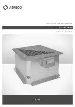
TECHNICAL AND MAINTENANCE DOCUMENTATION 

VTR-HD

WWW.AERECO.COM

4.  ELECTRICAL SPECIFICATIONS AND 

CONNECTIONS


― Connecting the HD automated system

The fan with a HD automated system should be connected as shown in the drawing.

To open the casing of a HD automated system use a screwdriver, do not use a power screw-

driver because of the danger of damaging the screws.

1

 PG11 cable gland enables connection of 1x230 V power supply. The power wires should 

be connected to the corresponding terminal blocks 

2

, according to the above drawing.

The potentiometer 

3

 is used to change the setting of the base pressure. The base pressure 

is preset at the factory. Do not change the default connections 

4

. The automated system 

is equipped with a switch 

5

. The switch-off button is located on the lower surface of the 

automated system.

After connecting the power supply, mount the cover of the automated system and tighten it 

with screws with 0.8 Nm force, use a torque screwdriver.

Type

Power supply

I max. [A]

P max. [W]

VTR-71

230 V AC/50 Hz

1.7

170

VTR-72

230 V AC/50 Hz

1.7

170

It is recommended to use an overcurrent circuit breaker.

The type of protection is selected by the electrical installation designer.

Summary of Contents for VTR-HD

Page 1: ...ROOF FANS VTR HD AERECO VENTILATION SYSTEM TECHNICAL AND MAINTENANCE DOCUMENTATION VTR HD ...

Page 2: ...olumes adapting to the lower airflow resistance in the ducts and increases the fan speed at higher airflow volumes caused by the open dampers of the hygroregulated grilles The HIGROdynamic automated system prevents improper operation of the ventilation system in particular excessive noise from grilles and diffusers at low humidity The automated regulation of operating parameters reduces the fan s ...

Page 3: ...aller is responsible for the compliance with all applicable safety regulations for electrical connections and protection against accidental contact Clearance must be provided around the fan the automated system and the measuring stub to allow for future maintenance The automated control system must be located in an easily accessible place When storing and assembling the fan the automated control s...

Page 4: ...onnected to the corresponding terminal blocks 2 according to the above drawing The potentiometer 3 is used to change the setting of the base pressure The base pressure is preset at the factory Do not change the default connections 4 The automated system is equipped with a switch 5 The switch off button is located on the lower surface of the automated system After connecting the power supply mount ...

Page 5: ...ing the voltage check that the fan works without any abnormal noises 6 USE The fans require periodical service twice a year which must include checking the general condition and cleaning the impeller and the housing Before operation service or repair of the device it is necessary to make sure that the employee performing the inspection has been trained and knows the safety rules the power supply i...

Page 6: ...uct name VTR 71 HD VTR 72 HD Equipped with HIGROdynamic HD automated systems 3 We declare the conformity of the product with the following directives standards and documents Directive 2014 30 EU Directive 2014 35 EU Directive 2006 42 EC European Commission Regulation 1253 2014 Łomna Las 12 March 2019 Marcin Gasiński Technical and Energy Requirements Specialist ...

Page 7: ...NOTES ...

Page 8: ...AERECO S A 62 rue de Lamirault Collégien 77615 MARNE LA VALLEE CEDEX 3 FRANCE www aereco com FLY730_v1_NOT_INST_VTR HD ...

Reviews: