7
5. OPERATION
5.1.
SET POINT IN COOLING MODE. PARAMETER 1STF
(factory
set)=7°C/44.9°F,
∆
t=9°C.
5.2.
SET POINT IN HEATING MODE. PARAMETER 3STC
(factory
set)
=
45C/113°F,
∆
t
=
9°C.
If
the
unit
power
supply
is
restored
after
a
temporary
interruption,
the
set
mode
will
be
kept
in
the
memory.
5.3.
COMPRESSOR START-UP DELAY
Two
functions
have
been
prepared
to
prevent
compressor
start
‐
ups
that
are
too
close.
‐
Minimum
time
from
last
switch
‐
off
180
seconds.
‐
Minimum
time
from
last
switch
‐
on
300
seconds.
5.4. CIRCULATION PUMP
The
circuit
board
delivers
an
output
for
pump
management,
which
starts
on
commissioning
and
remains
on
for
at
least
150
seconds
and
controls
the
state
of
the
probes.
After
the
first
40
seconds
of
pump
operation
the
water
flow
switch
closes
and
the
unit
starts,
when
the
water
flow
rate
is
in
normal
working
conditions,
the
water
flow
rate
alarm
functions
are
acti
‐
vated
(differential
pressure
switch
or
flow
meter).
When
the
ma
‐
chine
enters
stand
‐
by
mode,
the
pump
remains
on
for
30
sec
and
controls
the
flow
meter
or
the
pressure
switch
5.5.
FAN SPEED CONTROL
DCPX ACCESSORY
COOLING OPERATION AT LOW AMBIENT CONDITIONS
AND HEATING OPERATION AT HIGH AMBIENT CONDI-
TIONS.
To
allow
correct
functioning
of
the
unit
at
different
external
tem
‐
peratures,
the
MODUCONTROL
by
reading
the
pressure
via
the
pressure
probe,
controls
the
rotation
speed
of
the
fans,
thus
allow
‐
ing
to
increase
and/or
decrease
heat
exchange,
keeping
the
con
‐
densation
or
evaporation
pressures
more
or
less
constant.
The
fan
functions
independently
with
respect
to
the
compressor.
Remem
‐
ber
that
the
DCPX
is
mandatory
for
the
production
of
DHW.
And
cooling
below
20°C/68°F.
5.6. ANTI-FREEZE ALARM
The
anti
‐
freeze
alarm
is
never
active
if
the
machine
is
off
or
in
stand
‐
by
mode.
In
order
to
prevent
breakage
of
the
plate
heat
exchanger
due
to
freezing
of
the
water
it
contains,
the
MODUCONTROL
stops
the
compressor
if
the
temperature
detected
by
the
probe
postioned
at
the
outlet
of
the
heat
exchanger
and
in
inlet
to
the
chiller
is
below
+4°C/39°F.
THIS
ANTI
‐
FREEZE
SET
TEMPERATURE
CAN
ONLY
BE
VARIED
BY
AN
AUTHORISED
AFTER
‐
SALES
CENTRE
AND
ONLY
AFTER
HAVING
CHECKED
THAT
THERE
IS
ANTI
‐
FREEZE
SOLUTION
IN
THE
WATER
SYSTEM.
The
intervention
of
this
alarm
determines
compressor
stop
and
not
pump
block,
which
remains
active
along
with
the
switch
‐
on
of
the
resistance
if
installed.
To
restore
normal
functions
the
tem
‐
9.
The
voltage
is
within
the
tolerance
of
10%
of
the
unit
nominal
value
10.
Earthing
is
correctly
made.
All
electric
and
hydraulic
connections
are
correctly
tightened.
4.2. MACHINE COMMISSIONING
‐
Close
the
electric
control
board
hatch.
‐
Position
the
appliance
master
switch
at
ON.
‐
Make
sure
that
the
auxiliary
switch
contact
(IA)
(see
wiring
diagram)
is
open
(if
used,
and
the
display
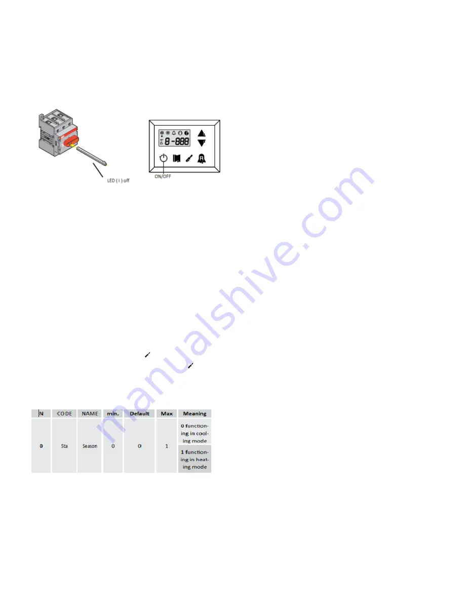
LED
(I)A
must
be
off.
‐
Press
the
ON
key
for
3
sec
to
switch
the
machine
on.
4.3. SEASON CHANGEOVER, OPERATION PARAMETERS
‐
For
every
season
change,
check
that
the
functioning
limits
lie
within
the
proper
limits.
‐
Check
that
the
compressor
input
current
is
lower
than
the
maximum
indicated
in
the
technical
data
table.
‐
Make
sure
that
the
voltage
value
lies
within
the
pre
‐
fixed
limits
and
that
unbalance
between
the
three
phases
(three
‐
phase
power
supply)
is
not
above
3%.
SEASON CHANGEOVER FROM PANEL ON MACHINE
Access
the
USER
SET
list
by
touching
the
insert
password
key
000
(already
displayed);
just
confirm
by
re
‐
pressing
the
key
The
parameter
affected
is
the
Sta,
changing
the
value
0
and
1
will
change
the
operation
from
cooling
to
heating
accordingly.
For
further
informa
‐
tion
refer
to
the
USER
MANUAL
SEASON CHANGEOVER FROM PR3
Just
act
directly
on
the
switch.
The
machine
switches
off
automatically
‐
and
switches
back
‐
on
with
the
selected
functioning
mode.
Advance
based
on
the
timeframe
for
the
completion
of
works
for
the
system.
Prior
to
the
work
to
be
carried
out
by
the
AERMEC
service
personnel,
all
other
works
(electrical
and
hydraulic
hook
‐
ups,
priming
and
bleeding
of
air
from
the
system)
must
have
been
completed.


