12
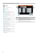
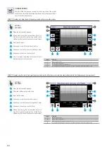
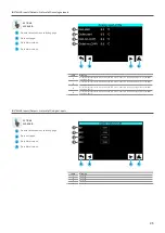
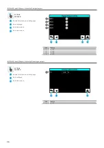
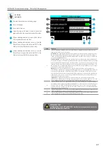
SYSTEM LAYOUT MENU
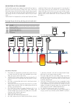
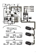
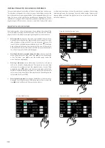
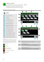
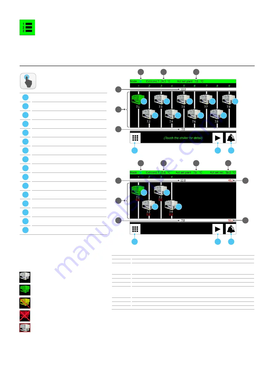
With the System layout menu you can monitor the overall state of the
chillers in the system; the inlet, outlet water values, chiller state (on,
off, in alarm, etc...), is all information available through this menu.
NOTE: the first page of this menu represents the home screen of the
application;
A
Open the menu selecting page
B
Go to next page
C
Go to alarms menu;
D
Open the CHILLER sub-menu (1);
E
Open the CHILLER sub-menu (2);
F
Open the CHILLER sub-menu (3);
G
Open the CHILLER sub-menu (4);
H
Open the CHILLER sub-menu (5);
I
Open the CHILLER sub-menu (6);
L
Open the CHILLER sub-menu (7);
M
Open the CHILLER sub-menu (8);
N
Open the CHILLER sub-menu (9);
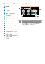
O
Open the MULTIPURPOSE sub-menu (1);
P
Open the MULTIPURPOSE sub-menu (2);
Q
Open the MULTIPURPOSE sub-menu (3);
R
Open the MULTIPURPOSE sub-menu (4);
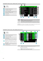
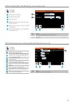
SYSTEM LAYOUT - Chiller main monitor (HOME)
Index
Meaning
1
Indicates the current functioning mode: cooling (
d
) or heating (
j
)
2
Current temperature value detected by the NTC probe connected to output U1 on the Multichiller-
Evo board. This probe must be installed outdoors in case of Air/water chiller or on the source return
in case of
Water/Water
chiller
3
Current temperature value set as work set
4
Current temperature value read by the NTC probe connected on the pCOe board input B1
5
Current temperature value read by the NTC probe connected on the pCOe board input B2
6
Each image displays one of the units currently controlled by the MULTICHILLER-EVO accessory. The
water value produced from the system side (white) and recovery unit side (red, only on multipurpo-
se units) is associated with every image
7
Current temperature value set as recovery side set
8
Current temperature value read by the NTC probe connected on the pCOe board input B3
9
Current temperature value read by the NTC probe connected on the pCOe board input B4
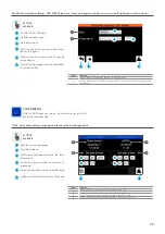
ACTIONS
AVAILABLE:
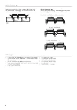
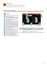
ATTENTION:
the CHILLER pages (which can be acti-
vated by pressing the corresponding icon) are only
available if the chiller has been provided during the
application loading phase; the current chiller status is
represented by the graphics assumed by each icon:
Chiller OFF
Chiller ON
Chiller in partial alarm
(works at reduced power)
Chiller in total alarm (chiller locked)
Chiller offline
1
4
A
B
C
2
3
5
D
E
F
G
H
I
L
M
N
1
A
B
C
2
3
O
P
Q
7
8
9
R
6
4
5
6
Summary of Contents for Multichiller-Evo
Page 2: ......


