background image

20

COMMISSIONING - WARNINGS

COMMISSIONING - WARNINGS

Please note that, on request by the Aermec customer or the legitimate 

owner of the machine, the units in this series can be started up by 

the AERMEC After-Sales Service in your area

 (valid only on ITALIAN 

territory). 

The start of operation must be scheduled in advance based 

on the time frame for the completion of works for the system. Prior to the 

intervention, all other works (electrical and hydraulic hook-ups, priming 

and bleeding of air from the system) must have been completed.

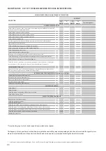
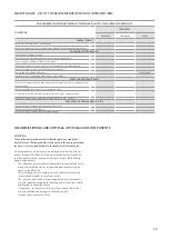
START-UP

OPERATIONS TO BE PERFORMED WITH NO VOLTAGE PRESENT

 ATTENTION 

the unit is not working:

Check:

-  All safety conditions have been respected

-  The unit is correctly fixed to the support surface

-  The minimum technical spaces have been respected 

-  That the main power supply cables have appropriate cross-section, 

which can support the total consumption of the unit. (see electric 

data sections) and that the unit has been duly connected to the 

ground.

-  That all the electrical connections have been made correctly and all 

the terminals adequately tightened.

-   Check for refrigerant gas leaks, especially near the pressure points 

of pressure gauges, pressure transducers and pressure switches. 

(vibrations during transport may have loosened the connections).

OPERATIONS TO BE PERFORMED WITH THE UNIT LIVE


ATTENTION 

the unit is still not working:

-  Supply power to the unit by turning the master switch to the ON 

position.

-  Use a tester to verify that the value of the power supply voltage to 

the phases is equal to 400V ± 10%; also verify that the unbalance 

between phases is no greater than 3%.

-  Check that the connections made by the installer are in compliance 

with the documentation.

-  Verify that the resistor of the compressor sump is working by 

measuring the increase in temperature of the oil pan. The resistance/s 

must function for at least 12 hours before start-up of the compressor 

and in any event, the temperature of the oil pan must be 10-15°C 

higher than room temperature.

HYDRAULIC CIRCUIT CONTROLS

-  Check that all hydraulic connections are made correctly, that the 

plate indications are complied with and that a mechanical filter has 

been installed in each inlet heat exchanger. 

(Mandatory component 

for warranty to be valid).

-  Make sure that the circulation pump/s is operating and that the 

water flow rate is sufficient to close the contact of the flow switch, if 

installed.

-  Check the water flow rate, measuring the pressure difference 

between inlet and outlet of the evaporator and calculate the flow rate 

using the evaporator pressure drop tables present in this manual.

-  Check the correct functioning of the flow meters if installed. Closing 

the cut-off valve at the output of the heat exchanger; the unit control 

panel must show the block. Finally re-open the valve and rearm the 

block

COMMISSIONING

-  Once all the aforementioned checks have been carried out, the unit 

can be commissioned

-  Close the door of the electrical panel.

-  Set the unit main switch to ON, the unit will start after a few minutes

OPERATIONS TO BE PERFORMED WITH MACHINE ON

 ATTENTION 

the unit is working:

Check:

-   That the compressor input current is lower than the maximum 

indicated in the electrical data table.

-   Before starting the unit, check that the compressor rotates in the 

correct direction through a three-phase protection. The spiral 

compressors compress in one direction of rotation only. Therefore, 

it is essential for the phase of the three-phase spiral compressors 

to be correctly connected (the correct direction of rotation can be 

controlled when the pressure on the intake side decreases and that 

on the flow side increases with the compressor in operation). If the 

connection is incorrect, the direction of rotation is reversed: this 

causes a loud noise and the reduction of current consumption. In this 

case, the protection system inside the compressor activated turning 

off the unit. To solve the problem, disconnect and swap the wires 

between two of the phases, then connect the three-phases again.

-   That the voltage value lies within the pre-fixed limits and that 

unbalance between the three phases (three-phase power supply) is 

not above 3%.

If having to take measurements and perform checks that require the 

machine to run, you must:  

-  make sure that any remote control systems are disconnected; 

however, keep in mind that the PLC on the machine controls its 

functions and can enable and disable the components creating 

hazardous situations (e.g. power and rotate the fans and their 

mechanical drive systems). 

-  Operate with the electrical board open the shortest time possible

-  Close the electrical board as soon as the single measurement or 

control is performed  

ATTENTION

The anti-freeze set temperature can only be varied by an authorised 

after-sales centre and only after having checked that there is a suitable 

% of anti-freeze solution in the water circuit.

Whenever this alarm intervenes, call the nearest authorised after-sales 

service immediately

- Control of the water flow rate alarm, the unit provides for the 

management of a flow rate alarm controlled by a differential pressure 

switch or flow switch if provided. This type of safety device intervenes 

after the first 30 seconds of pump functioning, if the water flow rate is 

not sufficient. The intervention stops the compressor and the pump 

itself.

Summary of Contents for NRB 0800

Page 1: ...BARCODE EN Installation and Maintenance Manual TRANSLATION FROM ORIGINAL 21 01 4138476_03 OUTDOOR INSTALLATION MICROCHANNEL COIL NIGHT MODE NRB H 0800 2400 60Hz...

Page 2: ......

Page 3: ...st grade materials and with cutting edge technology The quality level is being constantly monitored so AERMEC products are synonymous with Safety Quality and Reliability The data may undergo modificat...

Page 4: ...tronic Equipment WEEE please return the device using appropriate collection systems or contact the retailer where the product was purchased Please contact your local authority for further details Ille...

Page 5: ...NECTIONS 15 ELECTRIC POWER CONNECTION TO THE ELECTRICAL MAINS 16 ELECTRICAL DATA 208V 3 60HZ FAN J 17 ELECTRICAL DATA 230V 3 60HZ FAN J 17 ELECTRICAL DATA 460V 3 60HZ FAN J 17 ELECTRICAL DATA 460V 3 6...

Page 6: ...ecessary repairs The installation must comply with the requirements of EN378 3 and the local current regulations In particular indoor installation must ensure adequate ventilation and provide refriger...

Page 7: ...tures with ethylene glycol propylene in a maximum concentration of 30 The machine must only be employed for the use for which it was made any other use can be dangerous and void the warranty PreVentiO...

Page 8: ...etails of the problem to the shipping company within 48 working hours from delivery lifting Before lifting the unit place protections between the belts or ropes and chains and the framework to prevent...

Page 9: ...heck that the contact surfaces of the anti vibration supports are levelled to the base If necessary use spacers or level the base but in any case make sure that the anti vibration supports rest flat o...

Page 10: ...AA BH NRB n n in in in 0800 HA HE 3 6 97 87 156 0900 HA HE 4 8 97 87 203 1000 HA HE 4 8 97 87 203 1100 HA HE 4 8 97 87 203 1200 HA HE 4 8 97 87 203 1400 HA HE 5 10 97 87 250 1600 HA HE 6 12 97 87 297...

Page 11: ...ectric power board Unit Vers V block Fans Panel type A B C D E NRB H n n in in in in in 800 HA HE 3 6 1 39 43 39 32 118 900 HA HE 4 8 1 39 43 39 32 118 1000 HA HE 4 8 1 39 43 39 32 118 1100 HA HE 4 8...

Page 12: ...8 12 0 14 8 12 9 15 9 0 0 19 9 24 6 NRB 1100 HA HE 8995 100 48 9072 99 48 11 8 14 8 12 8 16 0 0 0 19 8 24 8 NRB 1200 HA HE 9237 99 48 9348 98 48 12 0 14 8 13 1 16 3 0 0 19 6 24 2 NRB 1400 HA HE 10538...

Page 13: ...in the highest points of the circuit and also provide discharge fittings in the lowest points to allow emptying the entire circuit To maintain the pressure in the circuits you must install an expansio...

Page 14: ...IL RISARCIMENTO DEI DANNI NE UTILIZZARE IL CONTENUTO O RENDERLO COMUNQUE NOTO A TERZI SENZA LA NOSTRA NON E PERMESSO CONSEGNARE A TERZI O RIPRODURRE QUESTO DOCUMENTO SOST DA SOST IL APPROV CONTR DISE...

Page 15: ...am fig 1 The use of an omnipolar magnet circuit breaker switch in compliance with the current Standards contact opening at least 0 12 in with suitable cut off power and differential protection on the...

Page 16: ...N TO THE ELECTRICAL MAINS 2 B F 3 31 03 2017 4 RIEPILOGOMORSETTI 5 E 1 31 03 2017 1 2 6 5 6 C D NOME FILE TIPICO SUBITI E FATTA RISERVA DI TUTTI I DIRITTI DERIVANTI DA BREVETTI O MODELLI AUTORIZZAZION...

Page 17: ...J 460V 3 60Hz fan J Units LRA MCA MOP Recommended fuse Phases Mod Comp Fan NRB Vers n n A A A n n 0800 HA HE 4 6 291 129 156 150 3 0900 HA HE 4 8 341 139 169 150 3 1000 HA HE 4 8 357 155 185 175 3 11...

Page 18: ...00 HA HE 4 14 575 254 306 250 3 2200 HA HE 5 16 600 298 350 300 3 2400 HA HE 6 16 506 348 398 350 3 575V 3 60Hz fan Units LRA MCA MOP Recommended fuse Phases Mod Comp Fan NRB Vers n n A A A n n 0800 H...

Page 19: ...VX1016 AVX1016 HE AVX1004 AVX1006 AVX1006 AVX1006 AVX1006 AVX1010 AVX1013 AVX1024 AVX1024 AVX1033 AVX1033 AVX Hydronic kit PA PB PC PD PE PF PG PH DA DB DC HA AVX1001 AVX1004 AVX1004 AVX1004 AVX1004 A...

Page 20: ...ure drop tables present in this manual Check the correct functioning of the flow meters if installed Closing the cut off valve at the output of the heat exchanger the unit control panel must show the...

Page 21: ...tivation before accessing them Isolate the unit from the mains by means of the external isolator provided for the insertion of padlocks up to 3 for blocking in open position Place a sign reading Do no...

Page 22: ...placed after draining the refrigerant gas contained in the circuit During venting protect yourself against any leakage of fluids at dan gerous temperatures and or pressures Always use appropriate equi...

Page 23: ...e machine panel where the control panel is located remaining distant and not exposed to the under pressure parts of the cooling circuit CLEANING COIL MICRO CHANNEL Keep surfaces clean battery mirco ch...

Page 24: ...particular attention to under pres sure containers In this case replace them of intervene with specific products General cleaning of the unit Bleed the hydraulic circuit and the heat exchangers the si...

Page 25: ...ctioning of the thermostatic valve Check the charge of refrigerant gas 1 Check the proper functioning of the solenoid valves MAINTENANCE LIST OF THE RECOMMENDED PERIODIC INTERVENTIONS DECOMMISSIONING...

Page 26: ......

Page 27: ......

Page 28: ...qua VR Italia Tel 39 0442 633111 Fax 39 0442 93577 marketing aermec com www aermec com Aermec reserves the right to make all modification deemed necessary for improving the product at any time with an...

Reviews: