18
EN
11.2.
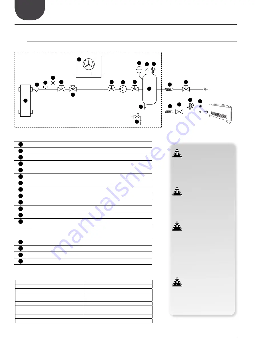
HYDRAULIC CIRCUIT (VERSIONS 03-04)
STANDARD COMPONENT
1
Exchanger plate
2
Free-cooling coil
3
Water filter
4
Ball stop
5
Flow switch
6
Air Vent
7
3-way valve
8
Pump
9
Expansion tank
10
Safety valve
11
Storage tank
12
Storage tank ball stop drain
13
Ball stop drain
RECOMMENDED COMPONENTS NOT SUPPLIED
(CHARGED TO THE INSTALLER)
14
Anti-vibration couplings
15
Ball stop
16
Charging unit
17
Manometer
6
1
2
3
4
4
5
6
7
10
13
15
16
17
8
14
14
4
11
15
12
9
hydraulic components NRL 03-04
hydraulic components NOT SUPPLIED
PH
6-8
Electric conductivity
less than 200 mV/cm (25°C/77°F)
Chloride ions
less than 50 ppm
Sulphuric acid ions
less than 50 ppm
Total iron
less than 0.3 ppm
Alkalinity M
less than 50 ppm
Total hardness
less than 50 ppm
Sulphur ions
none
ammonia ions
none
Silicone ions
less than 30 ppm
ATTENTION
The choice and the installation of
components external to the NRL
up to the installer, who must ope-
rate according to the rules of good
technical design and in compliance
with the regulations in force in the
country of destination.
ATTENTION
The hydraulic pipes connecting to
the machine must be properly si-
zed to the actual flow of water re-
quired by the system in operation.
The water flow to the exchanger
must always be constant.
ATTENTION
Carefully wash the plant, before
connecting the unit. This allows
cleaning to remove any residue
such as weld spatter, slag, rust or
other impurities from the pipes.
These substances may otherwise
accumulate in and cause a machi-
ne malfunction. The connecting
pipes should be supported so as
not to weigh, with their weight on
the unit.
ATTENTION
The hydraulic parallel is in charge
of the installer.
NOTE
The drawings are only examples
of the hydraulic circuit.
Summary of Contents for NRL 0280 FE
Page 2: ......


