6
20.05 – 4138421_03
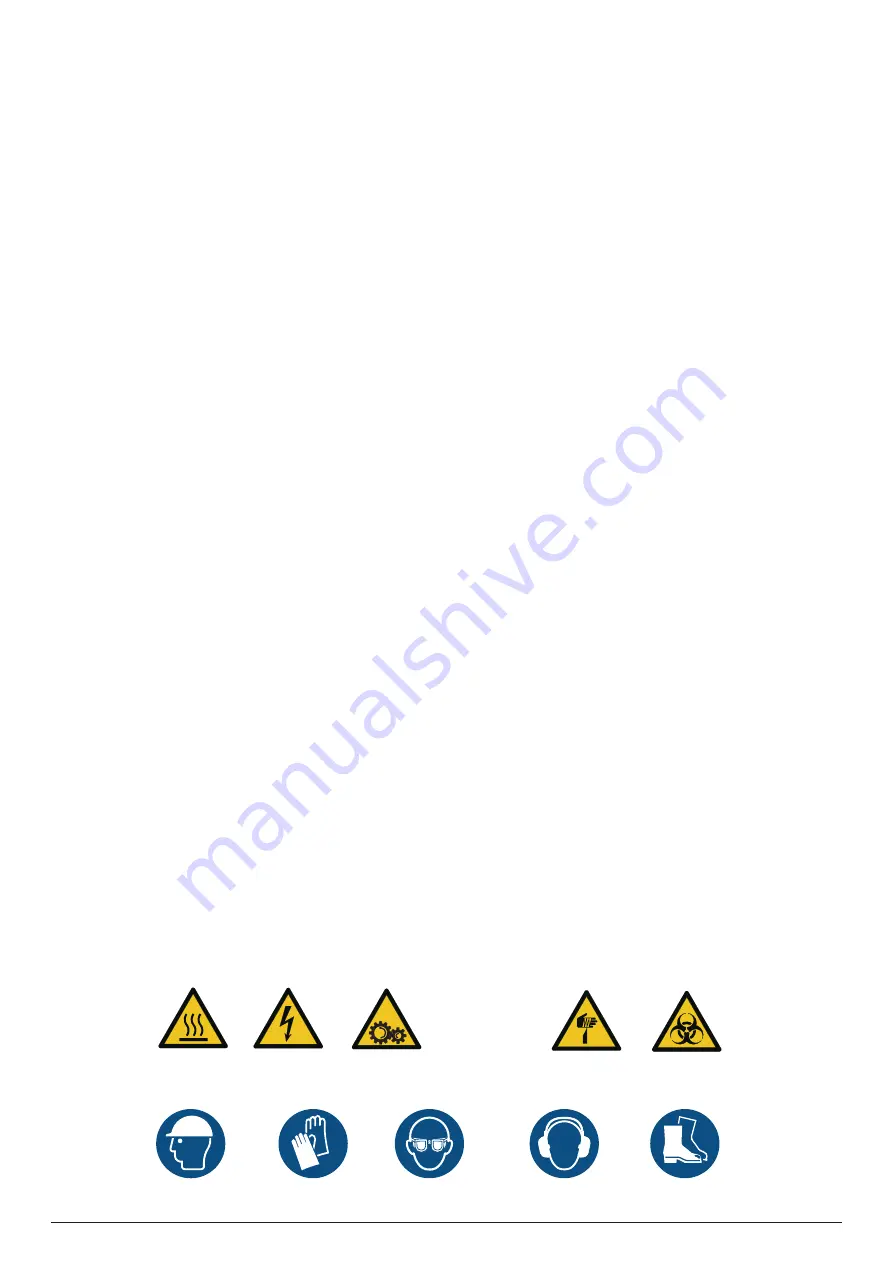
Warning;
Biological hazard
Electricity
Wear head
protection
Wear ear protection
Wear eye protection
Warning;
Sharp element
Wear protective
gloves
Wear safety
footwear
Warning;
Warning;
Warning;
Moving parts
Flammable material
Warning;
Hot surface
GENERAL WARNINGS
This product is a complex machine. Things and persons may be exposed
to risks during installation, operation, maintenance or repair, caused
by certain conditions or components, such as for example, but not
only, refrigerant, oils, moving mechanical parts pressure, heat sources,
electricity.
This products and its documentation, including this manual, are intended
for persons in possession of appropriate training to enable them to
operate correctly and safely. Before performing any operation on this
equipment, it is essential for the operating personnel to have read and
understood all manuals and any other material of reference. They must
also know and observe the standards applicable to the activities to be
performed.
ATTENTION
Any intervention on the unit must be performed by authorised
and qualified experienced technicians, in accordance with current
regulations.
The unit shows the following risks:
IMPORTANT GENERAL INSTRUCTIONS
• Risk of electric discharges.
• Risk of injuries due to rotating parts.
• Risk of injuries due to sharp edges and heavy weights.
• Risk of injuries due to high pressure gas.
• Risk of injuries due to high or low temperatures of components.
• Chemical risk
• Substances inside the water;
• In the event of the refrigerant catching fire, hazardous gases may be
generated.
It is vital that all work on the unit is performed in compliance with the
local standards. All work on the system must be performed to perfection
PRECAUTIONS AGAINST RESIDUAL RISKS
I
NSTRUCTIONS
- Install the unit according to the requirements herein
- Personnel that come into contact with the machine must be
competent in the use of this refrigerant and respect regulations
currently in force. Assess the procedures Aermec requires and
local fire prevention regulations to prevent inconsistencies in our
requirements and regulations currently in force.
- Regularly perform all maintenance operations provided for in this
manual
- Wear personal protective equipment
(gloves, eye protection,
helmet, …)
appropriate to the operations to be performed; do not
wear clothes or accessories that may get caught or be sucked by the
air flows; gather and tie your hair up before entering the unit
- The machine must be transported in compliance with current
regulations, taking into account the features of the fluids inside and
their characterisation described in the safety data sheet
- An inadequate transport may damage the machine, also generating
refrigerant leaks. Before commissioning, check for leaks and make any
necessary repairs.
- The installation must comply with the requirements of EN378-3 and
the local current regulations. In particular, indoor installation must
ensure adequate ventilation and provide refrigerant detectors when
necessary.
- The machine must not be installed in environments with risk of
explosion but in a suitable place. In particular, if intended for indoor
use, it cannot be installed outdoors
- The machines must be installed in structures protected from lightning
as provided by the applicable laws and technical standards
- The overall fire risk assessment at the place of installation (i.e. fire load
calculation) is the responsibility of the user.
- Keep fire extinguishers near the machine suitable for putting out
fires on electrical equipment and, for lubricant oil of the compressor
and the refrigerant as provided by the relative safety data sheets (for
example a CO
2
fire extinguisher)
- It is not permitted to walk or place other bodies on the machines
- Make the plant engineering connections to the unit according to the
instructions in this manual
- It is mandatory to install a water filter on the evaporator, penalty
invalidation of the warranty
- Do not bend or hit pipes containing under pressure fluids
Do not exceed the maximum allowable pressure (PS) of the unit’s
water circuit shown on the serial number plate
- Before removing elements along the under pressure water circuits,
shut-off the pipe section involved and gradually drain the fluid until
its pressure and that of the atmosphere are balanced.
- The unit contains under pressure refrigerant gas: no operation
must be performed on under pressure equipment except during
maintenance that must be carried out by competent and authorised
personnel
- Perform brazing or welding only on empty pipes and clear of any
lubricating oil residues; do not near flames or other heat sources to
the pipes containing refrigerant fluid
- Do not work with naked flames near the unit
- In order to avoid an environmental risk, make sure that any fluid leaks
are recovered in suitable devices in compliance with local regulations.
- Do not use your hands to control any refrigerant leaks
- An accidental release of refrigerant may cause risk of suffocation
due to a lack of oxygen: install the machine in a well ventilated
environment in accordance with EN 378-3 and local regulations
currently in force. Those who come into contact with the machine
must be equipped with a leak detector that is calibrated and
validated to reveal any used refrigerant leaks.
- The unit is fitted out with overpressure relief devices (safety valves):
in the event that these devices start, the refrigerant gas is released at
high temperature and high velocity.
Prevent the gas flow from harming people or things; if necessary,
channel the leak according to the EN 378-3 standard and local
regulations currently in force, paying particular attention to channel
fluids that pertain to safety groups other than A1 toward open and
secure spaces.
GENERAL WARNINGS
Summary of Contents for NYB
Page 2: ......


