background image

9

STA_STH_ 4804200 _02

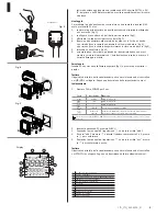
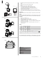
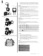
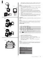
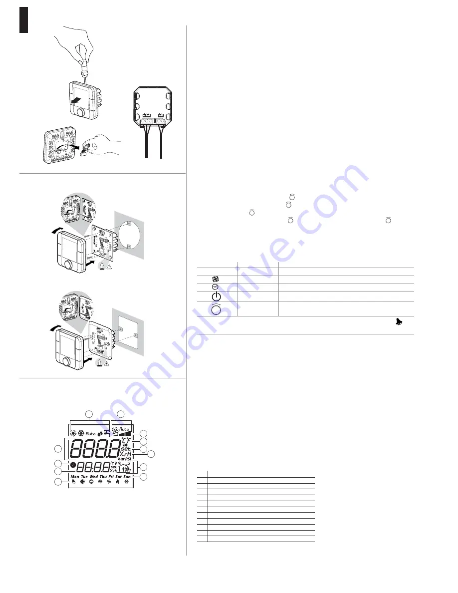
1.  separate the front of the terminal from the back using a screwdriver

( fi g.1);

2.  disconnect the 5-pin connector from the front

(fi g.2); 

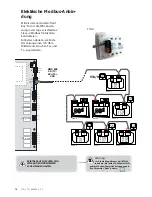
3.  make the electrical connections: see (fi g.3);
4.  fi x the back to the fl ush box with the two supplied screws:

• for round fl ush models, insert the screws as shown in (fi g.4);
• for rectangular fl ush models, insert the screws as shown in (fi g. 5);

5.  insert the 5-pin connector again;
6.  fi nally, reinstall the terminal, starting from the lower teeth with a hinge move-

ment. Make sure the electrical wires enter to have the correct snap connection.

Disassembly
Insert a screwdriver into the upper slot (Fig. 1) and press to remove the display 

Keypad
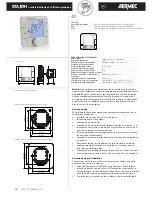
The meaning of the buttons and displays can vary depending on the control to 
which the STA/STH is connected. A description of the standard settings follows.
Addressing

1.  Press FAN and POWER for 5 sec.
2.  Enter the password 22, and press PUSCH
3.  Turning the adjustment knob 

-

+

PUSH

, search the wording “addr”.

4.  Having found “addr”, press 

-

+

PUSH

 and enter the address comprised between 

1 and 5, press 

-

+

PUSH

 to confi rm

5.  Turning the adjustment knob

-

+

PUSH

, search the wording “esc”, press 

-

+

PUSH

, to 

confi rm and exit.

Keypad

The meaning of the buttons and displays can vary depending on the control to 
which the STA/STH is connected. A description of the standard settings follows.

Key

Description

Pre-heating

mode

MODE

NOT USED

FAN

NOT USED

NOT USED

POWER

ZONE On/Off

Knob

Adjust.

allows you to change the setpoint. Turn the knob to set the 
value and press to confi rm

Access to special menus: MODE + CLOCK for 3s to access the alarms menu, active only if the 


icon is on.

-

+

PUSH

Fig.1

Fig.2

Fig.3

Fig.4

connections

Esploso AT******C*

click

4

5

6

click

4

5

6

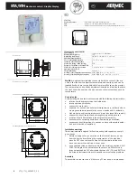
Display

1

3

4
5
6

8
9

10

12
11

7

2

1

Operating mode

2

Main fi eld

3

Fan speed in manual/automatic mode

4

Fan speed indication

5

Temperature reading unit

6

Set point

7

Relative humidity

8

Current time slot

9

Day of the week

10

Actuator on

11

Secondary fi eld

12

Time slots on

Fig.5

230 Vac

GND

Rx+/T

x+

Rx

–/T

x

N 230V~

L 50/60H

z

Summary of Contents for STA

Page 1: ... IT GB FR DE ES pag 4 pag 8 pag 12 pag 16 pag 20 Sonda temperatura ambiente umidità Room temperature probe humidity Sonde de température ambiante d humidité Raumtemperatur Sonde Feuchti gkeits Sonda de temperatura ambiente humedad ...

Page 2: ......

Page 3: ...erienze e di particolari studi di progettazione ed è stato costruito con materiali di primissima scelta e con tecnologie avanzatissime La marcatura CE inoltre garantisce che gli apparecchi rispondano ai requisiti della Direttiva Macchine Europea in materia di sicurezza Il livello qualitativo è sotto costante sorveglianza ed i prodotti AERMEC sono pertanto sinonimo di Sicurezza Qualità e Affidabili...

Page 4: ...izzati per montaggio ad incasso con scato la conforme alle normative vigenti 1 Prima di effettuare qualsiasi operazione sul terminale togliere l ali mentazione dal dispositivo portando l interruttore principale del qua dro elettrico su OFF rimuovere quindi la parte frontale del terminale e quindi quella posteriore per effettuare i collegamenti elettrici 2 per la connessione seriale utilizzare un c...

Page 5: ...crizione delle impostazioni comuni Indirizzamento 1 Premere FAN e POWER per 5 sec 2 Inserire la passowrd 22 premere PUSCH 3 Ruotando la manopola di regolazione PUSH cercare la scritta addr 4 Trovato addr premere PUSH e inserire l indirizzo compreso tra 1 e 5 preme re PUSH per confermare 5 Ruotando la manopola di regolazione PUSH cercare la scritta esc preme re PUSH per confermare e uscire Tastiera...

Page 6: ... N S N A001 ROHS ATA Code ATA GND Tx Tx 230V 50Hz CAREL Dara 06 N S N A001 ROHS ATA Code ATA GND Tx Tx 230V 50Hz CAREL Dara 06 N S N A001 ROHS ATA Code ATA GND Tx Tx 230V 50Hz CAREL Dara 06 N S N A001 ROHS ATA Code ATA GND Tx Tx 230V 50Hz CAREL Dara 06 N S N A001 ROHS ATA Code ATA ON 1 2 3 4 ON 1 2 3 4 Zona 2 Zona 3 Zona 1 Addr 1 Addr 2 Addr 4 Addr 5 Addr 3 Zona 2 Zona 2 Zona 3 Zona 3 FIELD BUS RX...

Page 7: ...ione fornita con il kit I dati tecnici riportati sulla seguente documentazione non sono impegnativi L Aermec si riserva la facoltà di apportare in qualsiasi momento tutte le modifiche ritenute necessarie per il miglioramento del prodotto Smaltimento del prodotto L apparecchiatura o il prodotto deve essere oggetto di raccolta separata in conformità alle vigenti normative locali in materia di smalti...

Page 8: ...m the device by switching the master switch of the electrical panel to OFF then remove the front of the terminal and then the back to perform the electrical connections 2 use a shielded three conductor cable for the serial connection AWG 20 22 The length of the network should not exceed 500m For very large networks add a 120 ohm resistor between RX TX and RX TX of the first and last terminal to av...

Page 9: ...press PUSCH 3 Turning the adjustment knob PUSH search the wording addr 4 Having found addr press PUSH and enter the address comprised between 1 and 5 press PUSH to confirm 5 Turning the adjustment knob PUSH search the wording esc press PUSH to confirm and exit Keypad The meaning of the buttons and displays can vary depending on the control to which the STA STH is connected A description of the sta...

Page 10: ... CAREL Dara 06 N S N A001 ROHS ATA Code ATA GND Tx Tx 230V 50Hz CAREL Dara 06 N S N A001 ROHS ATA Code ATA GND Tx Tx 230V 50Hz CAREL Dara 06 N S N A001 ROHS ATA Code ATA GND Tx Tx 230V 50Hz CAREL Dara 06 N S N A001 ROHS ATA Code ATA GND Tx Tx 230V 50Hz CAREL Dara 06 N S N A001 ROHS ATA Code ATA ON 1 2 3 4 ON 1 2 3 4 Zona 2 Zona 3 Zona 1 Addr 1 Addr 2 Addr 4 Addr 5 Addr 3 Zona 2 Zona 2 Zona 3 Zona ...

Page 11: ...sponsible The final customer must use the product only in the ways indicated in the documents supplied with the kit The technical data in the following documentation are not binding Aermec reserves the right to make all the modifications considered necessary for improving the product at any time Notes regarding the CE Declaration of Conformity The accessory described in this manual can only be use...

Page 12: ...l isolation Avertissements pour l installation Ces terminaux ont été conçus pour les encastrer en utilisant une boîte conforme aux normes en vigueur 1 Avant d effectuer toute opération sur le terminal couper l alimen tation du dispositif en plaçant sur OFF l interrupteur principal du ta bleau électrique retirer ensuite la partie avant du terminal et extraire enfin sa partie arrière pour réaliser l...

Page 13: ...une description des réglages les plus communs Adressage 1 Appuyer sur FAN et sur POWER pendant 5 s 2 Saisir le mot de passe 22 et appuyer sur PUSCH 3 Tourner la molette de régulation PUSH pour rechercher le mot addr 4 Une fois le mot addr trouvé appuyer sur PUSH et saisir l adresse comprise entre 1 et 5 puis appuyer sur PUSH pour confirmer 5 Tourner la molette de régulation PUSH pour rechercher le...

Page 14: ...C1 NO1 NO2 NO3 C2 NO4 NO5 NO6 NO7 C3 NC7 J7 J8 J9 J10 J11 J12 group 1 J13 group 1 J14 group 2 J15 group 3 RX TX RX TX GND GND T T GND T T GND Tx Tx 230V 50Hz CAREL Dara 06 N S N A001 ROHS ATA Code ATA GND Tx Tx 230V 50Hz CAREL Dara 06 N S N A001 ROHS ATA Code ATA GND Tx Tx 230V 50Hz CAREL Dara 06 N S N A001 ROHS ATA Code ATA GND Tx Tx 230V 50Hz CAREL Dara 06 N S N A001 ROHS ATA Code ATA GND Tx Tx ...

Page 15: ... considérée comme responsable Le client final doit utiliser le produit uniquement de la manière décrite dans la documentation fournie avec le kit Les données techniques indiquées sur ce document ne sont pas contractuelles Aermec se réserve la faculté d effectuer à tout moment toutes les modifications jugées nécessaires pour l amélioration du produit Note sulla dichiarazione di conformità CE L acce...

Page 16: ...n Rechtsvorschriften für die Unterputzmontage mit Einbaukasten gebaut 1 Bevor Arbeiten am Terminal in Angriff genommen werden dem Gerät den Strom entziehen indem der Hauptschalter des Schaltkastens auf OFF gedreht wird zuerst den vorderen Teil des Terminals und dann den hinteren Teil entfernen um die Stromanschlüsse durchführen zu können 2 für den seriellen Anschluss in 3 poliges geschirmtes Kabel...

Page 17: ...nden Sie die Beschreibung der allgemeinen Einstellungen Adressierung 1 FAN und POWER 5 Sek lang drücken 2 Das Passwort 22 eingeben PUSCH drücken 3 Den Einstellgriff PUSH drehen und den Text addr suchen 4 Nachdem addr gefunden wurde PUSH drücken und die Adresse zwischen 1 und 5 eingeben zum Bestätigen PUSH drücken 5 Den Einstellgriff PUSH drehen den Text esc suchen und zum Bestätigen und Verlassen ...

Page 18: ...t C1 NO1 NO2 NO3 C2 NO4 NO5 NO6 NO7 C3 NC7 J7 J8 J9 J10 J11 J12 group 1 J13 group 1 J14 group 2 J15 group 3 RX TX RX TX GND GND T T GND T T GND Tx Tx 230V 50Hz CAREL Dara 06 N S N A001 ROHS ATA Code ATA GND Tx Tx 230V 50Hz CAREL Dara 06 N S N A001 ROHS ATA Code ATA GND Tx Tx 230V 50Hz CAREL Dara 06 N S N A001 ROHS ATA Code ATA GND Tx Tx 230V 50Hz CAREL Dara 06 N S N A001 ROHS ATA Code ATA GND Tx T...

Page 19: ...ann Der Endkunde darf das Produkt nur auf die in der mit dem Kit gelieferten Vorgehensweise benutzen Die technischen Daten in der vorliegenden Dokumentation sind unverbindlich Im Sinne des technischen Fortschrittes behält sich die Aermec S p A vor in der Produktion Änderungen und Verbesserungen ohne Ankündigung durchzuführen Hinweise zur CE Konformitätserklärung Das in der vorliegenden Anleitung b...

Page 20: ...s requieren ser empotrados con caja conforme a las nor mativas vigentes 1 Antes de efectuar cualquier tipo de operación en el terminal desco nectar la alimentación del dispositivo colocando el interruptor principal del tablero eléctrico en OFF luego retirar la parte frontal del terminal y luego la parte trasera para efectuar las conexiones eléctricas 2 para la conexión serial utilizar el cable tri...

Page 21: ...una des cripción de los significados comunes Direccionamiento 1 Presionar FAN y POWER durante 5 seg 2 Ingresar la contraseña 22 presionar PUSCH 3 Girar el mando de regulación PUSH y buscar la leyenda addr 4 Al encontrar la leyenda addr presionar PUSH e ingresar la dirección com prendida entre 1 y 5 presionar PUSH para confirmar 5 Girar el mando de regulación PUSH buscar la leyenda esc presionar PU...

Page 22: ...3 C2 NO4 NO5 NO6 NO7 C3 NC7 J7 J8 J9 J10 J11 J12 group 1 J13 group 1 J14 group 2 J15 group 3 RX TX RX TX GND GND T T GND T T GND Tx Tx 230V 50Hz CAREL Dara 06 N S N A001 ROHS ATA Code ATA GND Tx Tx 230V 50Hz CAREL Dara 06 N S N A001 ROHS ATA Code ATA GND Tx Tx 230V 50Hz CAREL Dara 06 N S N A001 ROHS ATA Code ATA GND Tx Tx 230V 50Hz CAREL Dara 06 N S N A001 ROHS ATA Code ATA GND Tx Tx 230V 50Hz CAR...

Page 23: ...ble El cliente final debe usar el producto sólo en las modalidades descritas en la documentación entregada con el kit Los datos técnicos contenidos en este documento no son vinculantes AERMEC se reserva la facultad de realizar en cualquier momento todas las modificaciones que considere necesarias para mejorar el producto Notas sobre la declaración de conformidad CE El accesorio descrito en este ma...

Page 24: ...66 www aermec com I dati tecnici riportati sulla seguente documentazione non sono impegnativi L Aermec si riserva la facoltà di apportare in qualsiasi momento tutte le modifiche ritenute necessarie per il miglioramento del prodotto carta reciclata recycled paper papier recyclé recycled papier ...

Reviews: