background image

User Manual - URX_CF and URHE_CF -

6

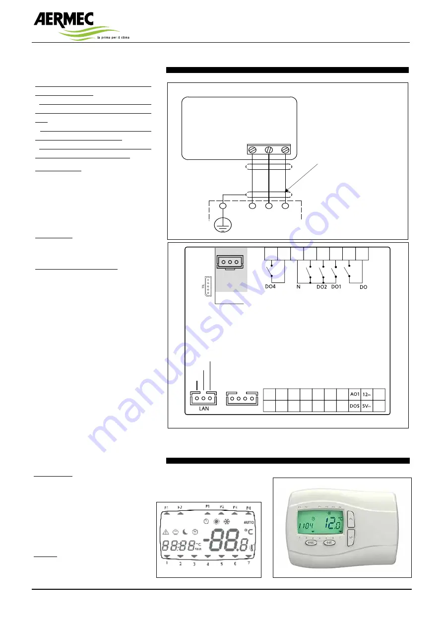
Remote keyboard connection

The following rules must be followed when 
doing the connections:
-  do not apply loads greater than the ones 
included in these specifications on the out-
puts;
-  when connecting the loads, carefully 
observe the connection diagrams; 
- keep the power cables separated from the 
signal cables to prevent interferences.

Analogue inputs 
The analogue inputs are 5: 
• 3 inputs for the NTC temperature 
probes; 
• 1 configurable input for NTC probe or 
for signal 4...20 mA. The following inputs 
are identified as AI1…AI5.

Digital inputs
The digital inputs, free from voltage, are 6 
and are identified below as ID1…ID6. 

Remote keyboard connection
Connect the three wires as per the wiring 
diagram.
Important! Do not connect the keyboard 
with the instrument powered on. Avoid 
the short-circuit between cables with the 
instrument powered on: they could dam-
age the instrument.

24: blue
25: red
26: Black

26

25

24

2525

2424

2626

TERMINALE REMOTO

REMOTE TERMINAL

24 25 26

MORSETTIERA 

QUADRO ELETTRICO

ELECTRIC TERMINAL

BOARD

User interface

User interface
The interface, consisting of the remote 
keyboard, makes it possible to carry out 
all operations related to the use of the 
instrument, in particular: 
• setting the operation mode 
• manage the alarm situations 
• check the status of resources 

Displays 
The device can communicate any type 
of information regarding its status, con-

no. 3 shielded electrical cables 
not shielded (max. length 100 m;  
minimum section 0.5 mm

2

)

Layout control unit rear view on the machine

FREE Smart 

13/61 


Modelli

 55xx  


x


5


uscite digitali

 tensione pericolosa 2A 230Vac 

ʅ

 [DO1, DO2, DO3, DO4, DO6] 

x


5


uscite analogiche

o


uscite analogiche

 [AO1, AO2] Open Collector PPM/PWM  

o


uscite analogiche

 tensione non pericolosa  (SELV (§))  

x


2 uscite [AO3-4] 0-10V 

x


1 uscita [AO5] 4…20mA/0…20mA 


x


ingressi digitali

 contatto pulito (°) [DI1…DI6] 

x


ingressi analogici


o


3 NTC* / Digital Input*** [AI1, AI2, AI5] 

o


2 NTC* / tensione, corrente** / Digital Input*** [AI3, AI4] 

x


1 uscita Open Collector PWM tensione non pericolosa  (SELV (§)) [DO5] 


*tipo  SEMITEC 103AT (10K

 / 25°C) 

**ingresso in  corrente 0…20mA/4…20mA oppure in tensione 0…5V / 0…10V / 0…1V  

oppure Ingresso digitale contatto pulito 

***ingresso digitale contatto pulito 

(°) corrente di chiusura riferita a massa 0.5mA 

(§) SELV: (SAFETY EXTRA LOW VOLTAGE)


x


SUPPLY   

Alimentazione 12-24V

a


/ 24V

c


x


c


Alimentazione Ausiliaria 5Vdc 20mA max 

x


12

 c


Alimentazione Ausiliaria 12Vdc 

x


N   Neutro 

x


LAN


collegamento a Terminale (KEYBoard) / SE6xx (max 100m) 

x


TTL


Seriale 

TTL

 per collegamento a Multi Function Key  

x


/C  


RTC  

x


RS-485  

/S 

Seriale RS-485 a bordo  

                                     per collegamento a sistemi di 

supervisione


/M Modbus Master


SMP55xx/C

SMP55xx/C/S

Supply
Supply

GND GND AI5

DI1

DI2

DI3

DI4

DI5

DI6

AO2

AI4

AI2

AI3

AI1

AO

DO3

DO3

RS-485

G

3

/S Models

only

5

4

+

-

G

RS-485

+

-

GG

SMD55xx/C/S(/M)

SMD55xx/C - SMD55xx/C/S

SMC55xx/C - SMC55xx/C/S

SE655

Supply

Supply

GND

GND

AI5

DI1 DI2 DI3 DI4 DI5 DI6 AO2

AI4

AI2 AI3

AI1

8

7

6

5

12

11

10

9

6

6

RS-485

/S Models

only

+

-

G

RS-485

+

-

GG

AO

G 3 5

4

RED

BLUE

BLACK

RED

BLUE

BLACK

figuration and the alarms through the 
display and LEDs on the front side.

Summary of Contents for URHE CF Series

Page 1: ...RECOVERY UNIT WITH COOLING CIRCUIT USER MANUAL URX_CF URHE_CF 0619 6193641_00 ...

Page 2: ......

Page 3: ... features 5 Remote keyboard assembly 5 Remote keyboard connection 6 User interface 6 Menu structure 8 Functions 9 Diagnostics 11 Use of the device 12 Liability and residual risks 12 Technical characteristics 13 RAEE Directive 13 ...

Page 4: ...refully all instruc tions next to the pictogram Failure to observe the instruc tions can lead to risk situations with possible consequent damages to the operator s and users health in general DANGEROUS VOLTAGE SIGN Observe carefully all instructions next to the pictogram The sign shows the components of the unit or in this manual identifies actions that could cause electri cal risks GENERAL PROHIB...

Page 5: ...irectly connected without serial interfaces electrical cable not provided RS485 serial board with series ModBus protocol Diagnostics The regulation system includes the notifi cation of the following faults defective temperature probe cooling circuit high and low pressure compressor thermal protection fan thermal protection Remote keyboard assembly The connection between the control board of the re...

Page 6: ... not shielded max length 100 m minimum section 0 5 mm2 Layout control unit rear view on the machine Modelli 55xx x 5 uscite digitali tensione pericolosa 2A 230Vac ʅ DO1 DO2 DO3 DO4 DO6 x 5 uscite analogiche o 2 uscite analogiche AO1 AO2 Open Collector PPM PWM o 3 uscite analogiche tensione non pericolosa SELV x 2 uscite AO3 4 0 10V x 1 uscita AO5 4 20mA 0 20mA x 6 ingressi digitali contatto pulito...

Page 7: ... cycle valve 4 water pump electric coil 5 alarm 6 free cooling Defrost LED ON if defrosting active OFF if defrosting disabled or finished BLINKING if time counting is in progress defrosting inter val Economy LED ON if the controller is in the economy mode Defrosting LED ON at the same time defrosting active Heating LED ON is the device is in the heating mode Cooling LED ON is the device is in the ...

Page 8: ...es Prof P1 Time Event1 P1 Mode Event1 TE10 TE37 HH MM State Machine St Actual state HCMode Ast Value Service Serv Password PASS Value Alarms Err Current error code ErXX Value Password level1 Operating Time Ohr Days Hours DayC HourC Value Filters Filt Filter counter td06 Filr td06 Value Password level 2 Compressor CP Filetr counter td06 COO C01 Value Allarm config All Low pressure Ct05 A01 A02 Valu...

Page 9: ...eventing thus the ener gy saving arising from the use of the colder outside air This relationship is valid if the outside temperature is lower than the cooling set the indoor temperature is greater than the outside temperature FREEHEATING The freeheating set is calculated by adding to the heating set the value equivalent to the parameter offset free cooling in heat In fact if the freeheating set c...

Page 10: ...possible stand by mode In case the above conditions are present the free cooling function is activated with null equivalent band full open or closed dampers if the opening of the damper was requested the fans are activated all other functions are disabled The function can be disabled in two ways by time out if the time bands are disabled by manual mode function change OFF time bands disabling TIME...

Page 11: ...ions block of the interested users notification on the keyboard display ALARM CODE DESCRIPTION AL01 Compressor maximum number of hourly activations exceeded AL22 High pressure on the cooling circuit alarm AL23 Low pressure on the cooling circuit alarm Er01 Er20 Wrong regulation temperature probe Er04 Clock error Er05 Anti freeze Er08 Remote panel communication error Er10 Compressor thermal protect...

Page 12: ...s class A device with regard to the software class and structure Non permitted use Any different use from the permitted one is forbidden It should be noted that the relay contacts are of the functional type and are subject to faults because they are controlled by an elec tronic part they can short circuit or remain open Possible protection devices according to the provisions of the product regulat...

Page 13: ...the environment and human health due to the presence of danger ous substances are listed inside this manual Further information if necessary can be requested to the manufacturer The RAEE directive provides that the dispos al and recycling of electrical and electronic devices as specified therein are compulsorily managed by a special collection separate from the one adopted for the dis posal or mix...

Page 14: ...NOTES ...

Page 15: ......

Page 16: ...9 0442 633111 Fax 39 0442 93730 39 0442 93566 http www aermec com The technical data given in the following documentation are not binding Aermec reserves the right at any time to make any modi fications deemed necessary for improving the product ...

Reviews: