


Heat recovery units with refrigeration circuit -
URX_CF
-
10
Selection and installation manual
GB
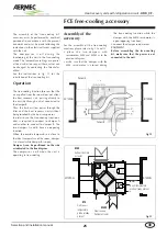
Operation
limits
In their standard set-up, the equipment
is not suitable for installation in a
saline environment. The maximum and
minimum limits of the airflow rate to the
exchanger are indicated by the curve of
the pressure drops diagram. Refer to fig.
043 for the operating limits.
N.B: Please contact Aermec technical
sales office in the event it is necessary
to operate the machine outside the
limits indicated in the diagram.
Summer mode:
Winter mode:
(heat pump)
fig.03
07 10 15 21 33
Max external temperature during cooling
°C
38
38
38
38
38
Min external temperature during cooling
°C
16
16
16
16
16
Max internal temperature during cooling
°C
34
34
34
34
34
Min internal temperature during cooling
°C
18
18
18
18
18
Min external temp with heat pump operating
°C
-10
-10
-10
-10
-10
Max external temp with heat pump operating
°C
24
24
24
24
24
Max internal temp with heat pump operating
°C
30
30
30
30
30
Min internal temp with heat pump operating
°C
14
14
14
14
14
Sound data
Sound pressure by band central frequence (Hz)
Sound pre. Sound Pre. Sound Pow.
63 125 250 500 1000 2000 4000 8000 Total Total
Total
dB
dB dB dB dB dB dB dB dB dB
(A)
dB
(A)
07
56
55 51 50 49 44 40 33
60
53 64
10
59
60 54 52 50 45 41 35
64
55 66
15
62
65 57 54 51 47 42 36
68
57 68
21
64
69 60 55 52 48 43 38
71
59 70
33
67
74 63 57 53 49 44 39
75
62 73
63
125
250
500
1000
2000
4000
8000
Sound pressure
dB
dB
dB
dB
dB
dB
dB
dB
dB dB (A)
07
65 57 54 57 54 50 53
48 67,0
60
10
66 58 56 60 57 57 57
52 68,8
64
15
67 59 58 62 60 61 63
57 71,1
68
21
66 61 58 67 62 65 68
63 73,8
72,5
33
69 61 59 64 71 71 63
58 76,1
75,5
Sound pressure measured at 3m distance from the free vent of the supply fan:
63
125
250
500
1000
2000
4000
8000 Sound power
dB dB dB dB dB dB dB dB dB dB
(A)
07
57 64 59 61 62 58 51
44 68,7
65,3
10
59 69 63 66 66 63 57
50 73,3
70
15
57 68 63 65 66 64 59
52 72,9
70,3
21
53 65 60 66 66 65 61
54 72,3
70,8
33
61 71 68 71 71 71 68
62 78,2
76,6
Sound power level from the supply vent:
• Attenuation of sounda data with SUF - Module with silencers (accessory)
63 125
250
500
1000
2000
4000
8000
dB dB dB dB dB dB dB dB
SUF
9 0 2 5 5 9 14
11
• Data outside the panel:
(
the data are calculated at the following conditions: 1 m. distance from the unit, ducted supply vent and in free fi eld)
• Sound data on the supply fan vent
-12
-10
-8
-6
-4
-2
0
2
4
6
8
10
12
14
16
18
20
22
24
26
12
14
16
18
20
22
24
26
28
30
32
14
16
18
20
22
24
26
28
30
32
34
36
38
40
16
18
20
22
24
26
28
30
32
34
36
t int (°C)
t int (°C)
t ext (°C)
t ext (°C)
Summary of Contents for URX CF
Page 2: ......
Page 31: ...NOTE ...
Page 32: ...NOTE ...
Page 33: ...NOTE ...
Page 34: ...NOTE ...
Page 35: ......


