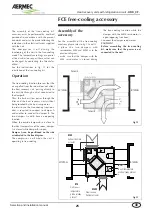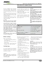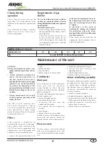
Heat recovery units with refrigeration circuit -
URX_CF
-
12
Selection and installation manual
GB
Fresh air temperature variations on the
change of the external air temperature
The following charts allow to determine
the variation of the temperature within
the room on the variation of the external
conditions. The variability of the air fl ow
is that allowed to guarantee that the
refrigerating circuit operates correctly.
N.B.
The following diagrams are typical for
all sizes, but without accessories
Summer use
X= T ext
Y = media
Δ
T
Q nom
Q nom-15%
Q nom+15%
26
-4,20
-5,21
-3,26
30
-1,18
-2,26
-0,36
34
0,00
-1,05
0,90
40
2,53
1,26
3,44
Winter use
X= T ext
Y = media
Δ
T
Q nom
Q nom-15%
Q nom+15%
-5
0,00
3,02
-1,84
0
2,73
5,25
0,26
5
5,56
8,27
3,07
10
8,67
11,53
6,38
15
11,89
14,58
9,36
20
15,09
18,03
12,70
-7
-6
-5
-4
-3
-2
-1
0
1
2
3
4
5
25
26
27
28
29
30
31
32
33
34
35
36
37
38
39
REGIME ESTIVO
Qnom.
Qnom-15%
Qnom+15%
V
ariation of the inlet air temperature
(°C)
Summer use
Winter use
V
ariation of the inlet air temperature
(°C)
External air temperature (°C)
At the nominal air flow
At the nominal air flow + 15 %
At the nominal air flow - 15 %
-5
0
5
10
15
20
-7 -6 -5 -4 -3 -2 -1 0 1 2 3 4 5 6 7 8 9 10 11 12 13 14 15 16 17 18 19 20 21
REGIME INVERNALE
Qnom.
Qnom-15%
Qnom+15%
At the nominal flow rate + 15 %
At the nominal flow rate - 15%
At the nominal flow rate
Conditions
:
exhaust air 26°, 50% R.H.
Conditions
:
exhaust air 26°, 50% R.H.
External air temperature (°C)
Summary of Contents for URX CF
Page 2: ......
Page 31: ...NOTE ...
Page 32: ...NOTE ...
Page 33: ...NOTE ...
Page 34: ...NOTE ...
Page 35: ......


