


Heat recovery units with refrigeration circuit -
URX_CF
-
7
Selection and installation manual
GB
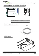
fig.02
Accessories
Available accessories
Mod.
07 10 15 21 33
MBC
MBC07 MBC10 MBC15 MBC21 MBC33
MBX
MBX07 MBX10 MBX15 MBX21 MBX33
G4F
G4F07 G4F10 G4F15 G4F21 G4F33
SUF
SUF07 SUF10 SUF15 SUF21 SUF33
FGC
FGC07 FGC10 FGC15 FGC21
-
FCE
FCE07 FCE10 FCE15 FCE21 FCE33
RBX
RBX
07 RBX10 RBX15 RBX21 RBH33
SUF
MBC
FGC
MBX -
RBX
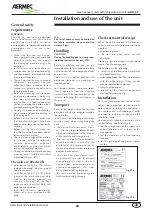
MBC Hot water coil module
This is an external module that can be
installed downstream from the motor fan
assembly on the fresh air flow, fitted with:
Two-row water heating coil with copper
pipes and aluminium fins with P2519
geometry. The manifold collectors are
equipped with a ½" G UNI 338 threaded
connector for the water inlet and outlet.
The three-way valves and related ON/
OFF actuator are also included.
MBX
Module with electric heating
battery
This is an outside module that can be
installed downstream from the motor fan
assembly on the fresh air flow, fitted with:
Electric heating element with armoured
finned elements equipped with double
safety thermostat with automatic and
manual reset.
RBX
Module with electric heating
battery
This is an outside module that can be
installed upstream from the motor fan
assembly on the fresh air flow, fitted with:
Electrical resistance in two-stage finned
armored elements with double safety
thermostat with automatic reset and
manual.
G4F
G4 efficiency filters
The units can be fitted with two cell-
type filters with corrugated septum
in class G4 according to the UNI EN
779 classification (weighted efficiency
of 90%) which can be placed as a
replacement of the G3 filters. The
filtrating cell is 48 mm thick.
SUF Module with silencers
The accessory is made up of two modules
that are equipped with silencer baffles
positioned on the supply and exhaust.
They are made of rockwool panels
with the surfaces in contact with the air
and protected by a polyester film held
between two galvanised and micro-
perforated laths.
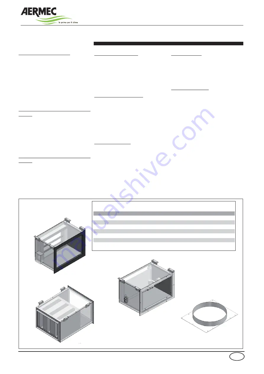
FGC circular flanges
The accessory is supplied as a single unit.
The accessory is made up of flanges
which connect to the rectangular port of
the unit so as to allow the use of circular
ducts.
The accessory is not available for size 33.
N.B. for further information, see the
tables in this manual and the various
accessories kits; see fig. 02 below
regarding compatibility
FCE Free-cooling
The “free-cooling kit ” includes 2
dampers with related ON/OFF 230V
servomotors.
For further information refer to the Use
manual.
RS485 Interface card
Interface card necessary for the interface
to supervisione systems according to the
MOD-BUS protocol.
Summary of Contents for URX CF
Page 2: ......
Page 31: ...NOTE ...
Page 32: ...NOTE ...
Page 33: ...NOTE ...
Page 34: ...NOTE ...
Page 35: ......


