19
© Aero-Stream, LLC 2022
102822 Rev. H
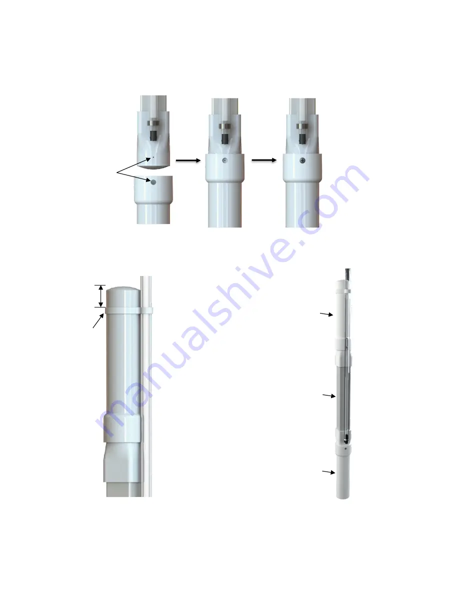
3. Slide ballast tube onto bottom of diffuser section (Figure 25) with a slight back and forth twisting
motion until the small hole on diffuser section is in the center of the large hole in ballast tube. Insert
screw and tighten until screw head is flush. Repeat process for attaching float tube to top of diffuser.
(See Figure 27)
Figure 25, Ballast and Float Tube Install
4. Slide air line
retainer towards top of float tube. Retainer should be approximately 1” below the top of
the float tube. See Figure 26.
Figure 26, Float Tube Air Line Detail
Figure 27, Diffuser Fully Assembled
Repeat step 2 through step 4 as needed for models containing multiple diffuser assemblies (AS1000-2
and AS1500-2).
1”
Air Line
Retainer
Alignment
Holes
Float Tube
(Top)
Ballast Tube
(Bottom)
Diffuser
Stone
Summary of Contents for AS1000-2
Page 8: ...8 Aero Stream LLC 2022 102822 Rev H Figure 4 Picture of the AS450 2 System ...
Page 9: ...9 Aero Stream LLC 2022 102822 Rev H Figure 5 Picture of the AS500 2 System ...
Page 10: ...10 Aero Stream LLC 2022 102822 Rev H Figure 6 Picture of the AS600 2 System ...
Page 11: ...11 Aero Stream LLC 2022 102822 Rev H Figure 7 Picture of the AS750 2 System ...
Page 12: ...12 Aero Stream LLC 2022 102822 Rev H Figure 8 Picture of the AS1000 2 System ...
Page 13: ...13 Aero Stream LLC 2022 102822 Rev H Figure 9 Picture of the AS1500 2 System ...


