25
© Aero-Stream, LLC 2022
102822 Rev. H
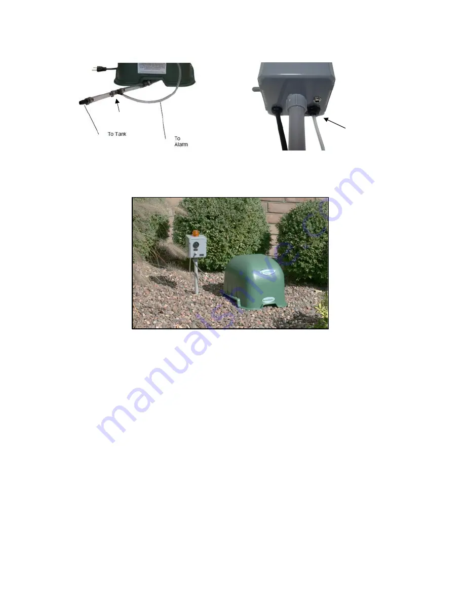
Figure 37, Fitting Installation
Figure 38, Underside of Alarm
Figure 39
,
Aero-Alert Installed
Install High Water Alarm Float
1. Per the approved plans, remove the tank lid on the predetermined install tank and determine the
depth of the water in the tank and record depth.
2. Determine the best location for the float mast so the movement of the float is not interfering with the
Bio-brush clusters. Position the mast in the tank corner with the float towards the corner typically works
best.
3. Back out the screws in the PVC receiver sections. See Figure 40
4. Insert the mast sections into the receivers with the section containing the float clamp at the upper
most position. Tighten the screws until the head of the screws bottom out on the receiver.
5. Using the measurement of the water depth in step 1, mark a line on the side of the PVC pipe
measuring from the bottom of the base towards the top end of the pipe. Slide the float clamp up or
down so the bottom of the clamp is 2 inches below the water mark and tighten clamp. See Figure 41.
1/8” Air Line into
Pressure Switch
Tee Fitting
Summary of Contents for AS1000-2
Page 8: ...8 Aero Stream LLC 2022 102822 Rev H Figure 4 Picture of the AS450 2 System ...
Page 9: ...9 Aero Stream LLC 2022 102822 Rev H Figure 5 Picture of the AS500 2 System ...
Page 10: ...10 Aero Stream LLC 2022 102822 Rev H Figure 6 Picture of the AS600 2 System ...
Page 11: ...11 Aero Stream LLC 2022 102822 Rev H Figure 7 Picture of the AS750 2 System ...
Page 12: ...12 Aero Stream LLC 2022 102822 Rev H Figure 8 Picture of the AS1000 2 System ...
Page 13: ...13 Aero Stream LLC 2022 102822 Rev H Figure 9 Picture of the AS1500 2 System ...


