26
© Aero-Stream, LLC 2022
102822 Rev. H
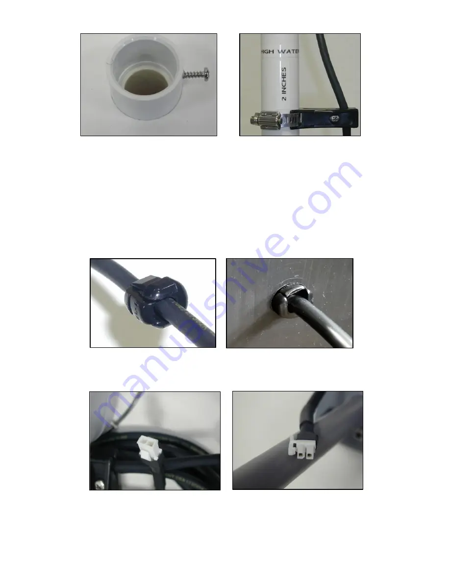
Figure 40, Screw Detail
Figure 41, Float Clamp
6. Drill a 5/8-inch hole through the side of the riser to allow the float switch cord to be pushed through.
Reference process in Figure 23 for detail.
7. Feed the free end of the float switch through the hole.
8. Pull the excess float switch cord through the hole and mark the cord at the point it exits the tank.
9. Install the strain relief around the cord at the mark. Grasping & compressing the strain relief with
pliers, push the strain relief into the 5/8-inch hole. Apply a bead of silicone sealant that meets ASTM C-
920 around the strain relief. See Figure 42.
Figure 42, Strain Relief
10. Plug the free end of the float switch wire into the wire connector on the Aero-Alert. See Figure 43.
Figure 43, Float Switch Connector (Left) and Aero-Alert Connector (Right)
11. Bury the float switch cord three-(3) to four-(4) inches below the ground surface.
Summary of Contents for AS1000-2
Page 8: ...8 Aero Stream LLC 2022 102822 Rev H Figure 4 Picture of the AS450 2 System ...
Page 9: ...9 Aero Stream LLC 2022 102822 Rev H Figure 5 Picture of the AS500 2 System ...
Page 10: ...10 Aero Stream LLC 2022 102822 Rev H Figure 6 Picture of the AS600 2 System ...
Page 11: ...11 Aero Stream LLC 2022 102822 Rev H Figure 7 Picture of the AS750 2 System ...
Page 12: ...12 Aero Stream LLC 2022 102822 Rev H Figure 8 Picture of the AS1000 2 System ...
Page 13: ...13 Aero Stream LLC 2022 102822 Rev H Figure 9 Picture of the AS1500 2 System ...


