20
4.
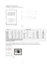
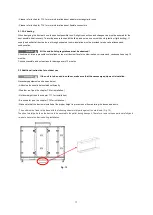
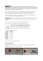
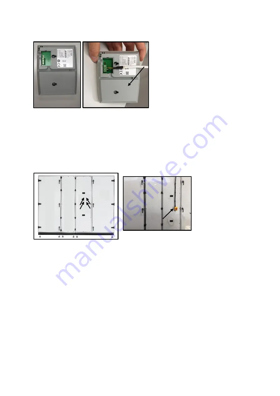
Connect the other end of the HMI cable with the display (Fig. 18) (refer to chapter 8 for connections)
2.3.3 Attachment of main switch
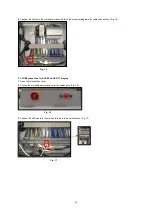
In EVO-50R, EVO-60R, EVO-R 8000, EVO-R 9500, EVO-R 12000, EVO-R 15000 models, the main switch must be mounted as
follows.
1.
Determine the service direction of the device.
2.
Connect the main switch with M4x10 bolt to the panel which is suitable for the service direction of the device. (Fig. 19)
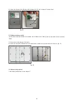
2.4 Commissioning assistant
Commissioning assistant can be seen chapter 4.1
HMI cable
Fig. 18
Fig. 19
Summary of Contents for EVO-R
Page 1: ...EVO R COMPACT AIR HANDLING UNIT WITH ROTARY HEAT RECOVERY ...
Page 129: ...129 Fig 170 Fig 171 ...
Page 130: ...130 Fig 171 ...
Page 132: ...132 Fig 173 Fig 174 ...
Page 133: ...133 Fig 174 ...
Page 135: ...135 Fig 176 Fig 177 ...
Page 136: ...136 Fig 177 ...
Page 138: ...138 Fig 179 Fig 180 ...
Page 139: ...139 Fig 180 ...
Page 141: ...141 Fig 182 Fig 183 ...
Page 142: ...142 Fig 183 ...
Page 144: ...144 Fig 185 Fig 186 ...
Page 145: ...145 Fig 186 ...
Page 147: ...147 Fig 188 Fig 189 ...
Page 148: ...148 Fig 189 ...
Page 150: ...150 Fig 191 Fig 192 ...
Page 151: ...151 Fig 192 ...
Page 153: ...153 Fig 194 Fig 195 ...
Page 154: ...154 Fig 195 ...
Page 155: ...155 ...

