background image

94 

5.

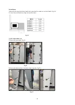
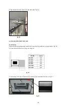
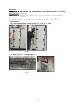
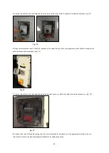
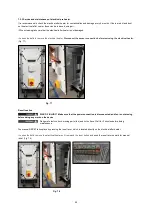
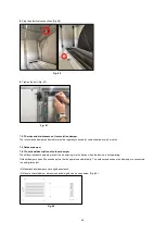
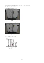
Connect the cables to the terminals and close the main switch cover. Refer to chapter 8 for cable connections. (Fig. 74)

6.

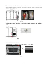
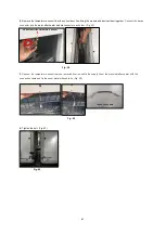
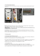
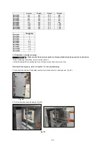
Open the terminal box cover. Check the thickness of the cable that you will use for signal connection. (Refer to chapter 8 for

cable thickness and connections) (Fig. 75)


7.

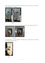
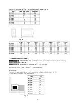
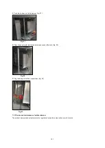
Connect the cables to the terminals and close the terminal box cover. Refer to chapter 8 for cable connections. (Fig. 76)

8.

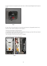
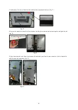
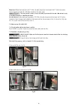
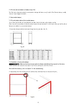
Connect other end of the cable coming from the electrical pre heater terminal box, to the appropriate terminal in the unit

terminal box. Refer to the electrical diagrams (chapter 8) for cable connections. 

Fig. 74 

Fig. 75 

Fig. 76 

Summary of Contents for EVO-R

Page 1: ...EVO R COMPACT AIR HANDLING UNIT WITH ROTARY HEAT RECOVERY ...

Page 2: ...ge 18 2 3 2 HMI connection for E3 DSP and ED T7 display Page 19 2 3 3 Attachment of main switch Page 20 2 4 Commissioning assistant Page 20 CHAPTER 3 FUNCTIONAL DESCRIPTION 3 0 Unit overview Page 21 3 1 Functions Page 25 3 1 1 Electrical pre heater Page 25 3 1 2 CAP mode Page 25 3 1 3 CRPM mode Page 25 3 1 4 VOD mode Page 25 3 1 5 Modbus Bacnet Page 25 CHAPTER 4 CONTROLLER 4 1 Commissioning Page 2...

Page 3: ...eek Program Page 45 c Holiday Page 46 d Extended Running Page 46 4 2 3 Ventilation on demand VOD Page 47 4 3 Functions Page 49 4 3 1 Recirculation Damper Page 49 4 3 2 Bypass Free Cooling Night Cooling Page 50 4 3 3 Emergency Operation Fire mode Page 51 4 3 4 Exchanger Deicing Page 51 4 3 5 Frost Protection WW Heating Coil Page 52 4 3 6 Filter monitoring Page 52 4 4 Priorities Page 52 4 5 User Lev...

Page 4: ...tion of cooling coil DX Page 102 7 7 2 Installation of cooling coil DX Page 102 7 7 3 Service and maintenance of cooling coil DX Page 105 7 8 Cooling coil water 7 8 1 Functional description of cooling coil water Page 107 7 8 2 Installation of cooling coil water Page 108 7 8 3 Service and maintenance of cooling coil water Page 110 7 9 Weather roof 7 9 1 Functional description of weather roof Page 1...

Page 5: ...2 Installation of FTF sensor Page 125 7 20 Signal converter 7 20 1 Functional description of signal converter Page 126 7 20 2 Installation of signal converter Page 126 7 21 Siphon for cooling module 7 21 1 Functional description of siphon for cooling module Page 126 7 21 2 Installation of siphon for cooling module Page 126 7 21 3 Service and maintenance of siphon for cooling module Page 127 CHAPTE...

Page 6: ... can be requested ex works Keep the installation and operating instructions as a reference at the device After the final assembly the document must be handed out to the operator tenant owner 1 1 Warning and safety instructions The following designations symbols are used in this manual to specify safety relevant information DANGER Death serious irreversible injury Indicates an extremely hazardous s...

Page 7: ...it types The scope of delivery also includes Door Handles Fixing clamp Gasket Dividable units Door handles are placed exhaust air fan side Fig 1 Please check delivery immediately on receipt for accuracy and damage If damaged please notify carrier immediately In case of delayed notification any possible claim may be void Unit EVO 15R EVO 20R EVO 30R EVO 50R EVO 60R EVO 80R EVO 95R EVO 120R EVO 150R...

Page 8: ...ays a risk that the lifting gear tackle ropes or slings are faulty or damaged Make sure that equipment is firmly seated before lifting it Risk of personal injury and equipment damage Due to a high center of gravity some equipment can tend to tip over and cause damage to persons and property When transporting the unit carefully observe its behavior and do not get near any possible hazardous areas D...

Page 9: ...ust be transported by forklift Provide a symmetrical load distribution before lifting the device Lift the device slowly Before transporting the device make sure that the forks of forklift truck are sufficient length that will come out from the opposite side of the device Fig 3 If the device is to be transported by crane the transport pipe entrances on the base must be used Fig 4 Fig 3 Fig 2 Fig 4 ...

Page 10: ...heat is transferred to the outdoor air depending on working conditions The supply air is led by the duct system to the primary supply air needing areas The used air is extracted from the secondary areas It flows back through the ducting to the ventilation unit transfers the heat and is discharged by the exhaust air duct to the atmosphere The AERA EVO R units are only intended for handling of air a...

Page 11: ...3 400V 50Hz 3 400V 50Hz 3 400V 50Hz 3 400V 50Hz 3 400V 50Hz 3 400V 50Hz 3 400V 50Hz 3 400V 50Hz Filter class extract outdoor air ePM10 50 ePM1 55 ePM10 50 ePM1 55 ePM10 50 ePM1 55 ePM10 50 ePM1 55 ePM10 50 ePM1 55 ePM10 50 ePM1 55 ePM10 50 ePM1 55 ePM10 50 ePM1 55 ePM10 50 ePM1 55 Weight kg 230 300 361 629 775 930 1090 1190 1500 IP Class with weather roof IP54 IP54 IP54 IP54 IP54 IP54 IP54 IP54 IP...

Page 12: ...on For safety reasons use compressed air to blow through the system in order to remove all remaining water Risk of personal injury and equipment damage Due to a high center of gravity some equipment can tend to tip over and cause damage to persons and property When transporting the unit carefully observe its behavior and do not get near any possible hazardous areas 1 11 Disposal Before starting an...

Page 13: ...peline due to these features They reduce losses and increase the degree of efficiency of the system Important notes The ventilation ducts must not become kinked The connections to the connection valves must be firm and tight Flange connections must be leakproof and firm If necessary vibration isolators can be used between unit and floor Make sure that sufficient duct length is available before con...

Page 14: ...formation on transport of EVO R unit please refer to chapter 1 6 2 1 1 Leveling of unit EVO R has easily adjustable feet Make sure that the device is placed on a flat surface before any assembly work Change the height of the feet to leveling the device Height H can be maximum 90mm Fig 6 2 1 2 Attachment of door handles The door handles are packaged separately to avoid damage during the transport I...

Page 15: ...ce Before assembling the modules apply gasket between adjacent modules Fig 8 Before joining the modules for final assembly position them as close to one another as possible Use the unit base frame only to pull the modules together 1 Bring modules closer together and plug the electrical connections Fig 9 2 Tighten the bolt Fig 10 Fig 10 Fig 9 Fig 8 ...

Page 16: ...K L EVO 15R 350 310 14 14 0 0 378 28 338 28 EVO 20R 470 310 14 14 0 0 498 28 338 28 EVO 30R 580 410 14 14 1 304 1 0 30 608 28 438 28 EVO 50R 855 410 14 14 1 441 6 0 30 883 28 438 28 EVO 60R 855 410 14 14 1 441 6 0 30 883 28 438 28 EVO 80R 1055 410 14 14 2 361 1 0 30 1083 28 438 28 EVO 95R 1200 410 14 14 2 409 4 0 30 1228 28 438 28 EVO 120R 1475 510 14 14 2 501 1 1 269 1 30 1503 28 538 28 EVO 150R ...

Page 17: ...ntamination corrosion and condensation every 12 months Check accessible air duct sections for damage every 12 months 2 2 Additional instruction for outdoor use If the unit is to be used in outdoor make sure that the necessary equipment is installed Necessary equipment can be seen below All ductworks should be insulated sufficiently Weather roof see the chapter 7 9 for installation Outdoor spigot s...

Page 18: ...le has two different optional lengths 10m 20m According to EN 61000 3 2 these devices are to be classified as professional devices Connection to a low voltage supply public networks is allowed insofar as this has been clarified with the respective energy supply company responsible Please refer to chapter 7 for more information about power supply connection of accessories These circuit breakers rec...

Page 19: ...diagrams for cable connections Fig 15 2 3 2 HMI connection for E3 DSP and ED T7 display 1 Open the terminal box cover 2 Loosen the marked grommet and enter the cables here Fig 16 3 Connect the HMI cable to the marked terminals in the terminal box Fig 17 Fig 15 Fig 16 Fig 17 ...

Page 20: ...R 8000 EVO R 9500 EVO R 12000 EVO R 15000 models the main switch must be mounted as follows 1 Determine the service direction of the device 2 Connect the main switch with M4x10 bolt to the panel which is suitable for the service direction of the device Fig 19 2 4 Commissioning assistant Commissioning assistant can be seen chapter 4 1 HMI cable Fig 18 Fig 19 ...

Page 21: ...3 0 Unit overview Non dividable unit EVO 15R EVO 20R EVO 30R Sectional view of standard unit including internal accessory Fig 20 Outer view including weather roof and outdoor spigots Fig 21 1 10 4 5 8 8 2 7 9 6 3 11 Fig 20 Fig 21 12 13 14 ...

Page 22: ...ptional 5 Extract air filter ePM10 50 6 Outdoor air main filter ePM1 55 7 Rotary heat exchanger 8 Outdoor damper optional 9 Water after heater or electrical after heater optional 10 Main switch 11 Casing 12 Weather roof optional 13 Exhaust air spigot optional 14 Outdoor air spigot optional ...

Page 23: ...50R EVO 60R EVO 80R EVO 95R EVO 120R EVO 150R Sectional view of standard unit including internal accessory Fig 22 Outer view including weather roof and outdoor spigots Fig 23 8 10 1 6 2 8 7 4 5 9 3 11 Fig 22 Fig 23 12 13 14 ...

Page 24: ...r ePM10 50 optional 5 Extract air filter ePM10 50 6 Outdoor air main filter ePM1 55 7 Rotary heat exchanger 8 Outdoor damper optional 9 Recirculation damper optional 10 Main switch 11 Casing 12 Weather roof optional 13 Exhaust air spigot optional 14 Outdoor air spigot optional ...

Page 25: ...tely for supply air fan and exhaust air fan 3 1 3 VOD Mode VOD mode is used for air quality of the area via air quality sensors CO2 FTF VOC This mode can also be used when multiple sensors are installed If there are more than 3 air quality sensors then a signal selector should be used Signal selector chooses the biggest value of the sensor feedback voltage to run the VOD scenario 3 1 4 Modbus Bacn...

Page 26: ...ts the commissioning wizard must be called up again 4 1 1 Calling the Commissioning Assistant Wizard Step1 Log in as an Admin Access rights Activate wizard Press the LEFT direction button to return to the Main Menu By selecting Configuration input is entered with RIGHT direction button Press the UP DOWN direction button to select System Menu By pressing RIGHT direction button to enter System Menu ...

Page 27: ...istant wizard only German French English and Turkish are available German French Finnish Russian Polish Hungarian Czech Lithuanian Estonian Latvian Slovenian Spanish Portuguese Italian Slovak Dutch Turkish Dutch Romanian English Swedish Norwegian Danish 4 1 2 Device Selection Selection of the applicable ventilation unit in 3 groups Ceiling unit with counter flow exchanger for the device series AZU...

Page 28: ...d cooling registers Electrical heating WW heating DX Cooling CW Cooling The control function mode is defined only by the commissioning assistant wizard The following temperature control modes are available a Constant Supply Air b Outdoor Compensated Supply Air c Cascade Room Temp Control d Cascade Extract Air Control e Outdoor Dependent Supply or Room Temp f Outdoor Dependent Supply or Extract Tem...

Page 29: ...ture is in the neutral zone heating and cooling are blocked If the supply air temperature falls below the SetPoint NZ 2 heating is active until the set point is reached If the supply air temperature rises above the SetPoint NZ 2 cooling is active until the set point is reached The set point is in the menu Temperature log in as User or admin Alarms triggered by too high or low supply air temperatur...

Page 30: ...uring the cold season The setpoint of the supply air temperature is determined outside temperature dependent by means of a control curve with 8 points Example Outdoor temperature C Supply Temperature C 20 25 15 24 10 23 5 23 0 22 5 20 10 18 15 18 Control function Mode Outdoor comp supply Outdoor comp setp 20 0 C 25 0 C 15 0 C 24 0 C 10 0 C 23 0 C Outdoor comp setp 5 0 C 23 0 C 0 0 C 22 0 C 5 0 C 2...

Page 31: ...int of the supply air temperature according to the deviation of the ambient temperature from the room temperature setpoint The room temperature SetPoint is in the menu Temperature log in as User or admin d Cascade Extract Air Temperature Control The cascade control of the extract air and supply air temperature is used to maintain a constant adjustable room temperature The output signal of the extr...

Page 32: ...input AI2 at the controller If the outside temperature is below the adjustable limit winter outdoor compansated supply air temperature control will be active see b Otherwise summer the Cascade Room Temp Control see c is active Extract air temp Setp XX X C Control function Mode Room Supply air Supply air temp Setp XX X C Room temp Setp XX X C Outdoor temp for Control mode change XX X C ...

Page 33: ... FTF accessory Connection of the analog output A2 temperature signal of the KWL FTF to the analogue input AI2 at the controller The room temperature can be adapted when the outside temperature rises For example at higher outside temperatures a slightly higher room temperature may be acceptable or a slightly lower in cooler weather conditions This temperature control mode is used to conserve energy...

Page 34: ...oor temperature C Room Temperature C 20 18 15 18 10 20 5 22 0 23 5 23 10 24 15 25 Control function Mode Outd comp room Outdoor comp setp 5 0 C 23 0 C 0 0 C 22 0 C 0 C 20 0 C Outdoor comp setp 20 0 C 25 0 C 15 0 C 24 0 C 10 0 C 23 0 C Outdoor comp setp 10 0 C 18 0 C 15 0 C 18 0 C If cascade control Max min supply setp Max XX X C Min XX X C ...

Page 35: ...air temperature may be acceptable or a slightly lower in cooler weather conditions This temperature control mode is used to conserve energy Control function Mode Outd comp extr air If cascade control Max min supply setp Max XX X C Min XX X C Outdoor comp setp 20 0 C 25 0 C 15 0 C 24 0 C 10 0 C 23 0 C Outdoor comp setp 5 0 C 23 0 C 0 0 C 22 0 C 0 C 20 0 C Outdoor comp setp 10 0 C 18 0 C 15 0 C 18 0...

Page 36: ...t fans are set in m3 h in constant air flow mode in constant RPM mode Pa in constant pressure mode by the Up Down direction buttons by pressing OK key Then press to OK button again to confirm The functions that can be selected for the ventilation mode are listed below Constant air flow m3 h Constant RPM Constant pressure Pa a Constant air flow 3 Ventilation levels are available Reduced Normal Boos...

Page 37: ...possible in the supply air and the extract air duct 1 ventilation level is available Normal If you select a different level of ventilation minimal intensive from the ventilation mode menu The ventilation unit always runs at the set pressure setpoint The set point is predefined during commissioning via the commissioning assistant Operation of the ventilation unit is not possible while the assistant...

Page 38: ...deactivate electrical preheating By default electrical preheater is deactived The electric preheating is used exclusively to prevent the freezing of the heat exchanger Press the OK button in electrical preheater menu to activate or deactivate electrical prehater By pressing UP DOWN direction button to select YES NO 4 1 7 Supply Air filter Type The following filter types are available ePM1 55 F7 eP...

Page 39: ...register Electrical electrical heating register In the after heater type menu with the OK button the after heater type is selected with the UP DOWN direction buttons and the OK button is pressed to confirm 4 1 10 Cooler Selection of the available cooler types The following selection is available None Water CW cooling register DX DX cooling register In the cooler type menu with the OK button the co...

Page 40: ...ature activation set value for free cooling and press OK button to select the temperature The Outdoor temperature night menu is entered with the OK button The high and low limits of the free cooling outdoor air temperature are set by the UP DOWN direction buttons Press the OK button If the outside temperature is higher than the set High value or the outside air temperature is below the set Low val...

Page 41: ...at output after freecooling menu press the UP DOWN buttons to set the heating outputs to be blocked for a few minutes and press the OK button to confirm All units have an ODA temperature sensor as a standard In the outdoor sensor placed in intake channel menu is entered with OK button With the UP DOWN direction buttons it is selected as YES and OK button is pressed to confirm 4 1 13 Ventilation on...

Page 42: ...an set by the UP DOWN direction buttons and press OK to confirm To perform sensor settings o Reduced Activation of the ventilation level minimal from this sensor value o Boost Activation of the ventilation level intensive from this sensor value o Diff hysteresis o Stop time As soon as the ventilation unit is on the ventilation level for more than time set sensor controlled ventilation is terminate...

Page 43: ...4 for air quality sensors are available If more than 3 sensors are to be connected The signal converter with 6 analogue inputs and an analogue output available Only the same type of sensors can be connected to one AIR1 SK 4 1 14 Leaving the commissioning assistant By selecting Yes at accept all settings menu the controller will restart to start the desired application The device can now be put int...

Page 44: ...r must be set to zero 4 2 2 Timers The device runs only after the set time intervals of the Timers For the use of the Timers must be in the menu mode Timers be set If Timers is selected and no switching contacts are active the device runs only according to the Timer settings If there are several timers active at the same time the function with the highest priority is active No active Timers means ...

Page 45: ...ories required sensor operated operation Timer Recirculation accessories required not available on XC equipment At times when no ventilation levels function is selected the device does not run standby Setting the weekly program Login as user or admin Call Up the Timer settings menu Call up the desired Timer Set Timer for all days Temperature Air control Time settings Access rights Time Date Timer ...

Page 46: ...eed timer normal speed or timer boost speed are in operation at the same time because it has a lower priority c Holiday The Timer settings has a programmable holiday calendar with up to 24 holiday periods per year Setting the holiday calendar Login as user or admin Calling the Timer settings menu Holiday Day according to setting of the Days Week programs program The ventilation unit always runs du...

Page 47: ... The power supply 24 VDC is connected according to the wiring diagram Refer to chapter 8 The signal cables are connected according to the wiring diagram Refer to chapter 8 via the analog inputs AI2 AI3 and AI4 When connecting to note If a room temperature sensor is used on analog input AI2 only the analog inputs AI3 and AI4 for air quality sensors are available Up to 3 different type of sensors ca...

Page 48: ...O R 30 60W EVO R 50 60W EVO R 60 75W EVO R 80 75W EVO R 95 75W EVO R 120 75W EVO R 150 75W Calculation basis KWL CO2 200 mA KWL FTF 30 mA KWL VOC 40 mA AIR1 CO2 K 200mA Settings for the sensor controlled operation The settings are made in the commissioning wizard Activation boost speed Ventilation Activation Reduced speed Ventilation Diff Diff Boost speed ventilation Reduced speed ventilation Vent...

Page 49: ...ement 4 3 Functions 4 3 1 Recirculation damper In recirculation mode the extract air is 100 returned to the supply air During recirculation mode a separate temperature setpoint and a fan offset are available To use the recirculation mode it must first have been activated in the commissioning wizard see chapter 1 commissioning Settings for the recirculation mode Log in as admin Call up the Temperat...

Page 50: ... In order to use the free cooling system it must be activated in the commissioning assistant wizard In order for the free night cooling to be active the following conditions must be met The unit has been in operation within the last 4 days The outside temperature was above the set limit XX c during operation It is between XX XX and XX XX am adjustable The following Timer are turned off Timer VOD T...

Page 51: ...until an exhaust temperature of 4 c has been reached If the pre heating is running for more than 3 minutes to 100 the second stage of icing protection is changed EVO R Activation and control of the preheating as soon as the outside air is lower than 8 c and exhaust air is less than 0 c The preheating remains active until an exhaust temperature of 4 c has been reached If the pre heating is running ...

Page 52: ...alarm is triggered 4 4 Priorities If several ventilation requirements are active at the same time the ventilation unit runs with the respective ventilation level which has the highest priority This means for example that the external switching contact overrides all other ventilation requirements Priority list highest up External switching contact Fire Emergency Contact Manual operation with HMI or...

Page 53: ...s are lost a current master password can be requested AERA customer service View the following menus Only with operating level at least Operating mode No rights Temperature No rights Fan control No rights Timer No rights Selected Functions Pure display menu No rights Alarms Pure display menu No rights Manual Auto Service Configuration Service Settings Service Commissioning assistant Wizard Log in ...

Page 54: ...on C No Check running mode 35 Ventilation manual operation C No Check running mode 36 Manual operation supply air control C No Check running mode 37 Manual operation supply air fan mode C No Check running mode 38 Manual operation frequency control supply air C No Check running mode 39 Manual operation exhaust fan mode C No Check running mode 40 Manual operation frequency control exhaust Air C No C...

Page 55: ... unit 4 124 Communication error expansion unit 5 C No Check communication cable connection of expansion unit 5 125 Communication error expansion unit 6 C No Check communication cable connection of expansion unit 6 ...

Page 56: ...MODEL A B C Cmin Cmax D E F K L M N U V X Y Z Dimensions mm Fig 24 EVO 15R 1295 990 155 135 180 1700 760 910 205 360 415 520 378 338 350 310 100 EVO 20R 1400 1090 155 135 180 1700 860 1010 205 360 415 520 498 338 470 310 100 EVO 30R 1500 1200 155 135 180 1700 970 1120 205 360 415 520 608 438 580 410 100 Fig 24 ...

Page 57: ...57 MODEL AA BB CC DD EE FF GG HH Dimensions mm Fig 25 EVO 15R 655 568 472 143 5 150 463 2 263 4 380 EVO 20R 640 568 472 193 5 150 514 2 286 4 430 EVO 30R 655 568 472 250 150 573 2 313 4 485 Fig 25 ...

Page 58: ... 135 180 2315 1710 1860 1891 830 1480 775 EVO 120R 2400 2090 155 135 180 2450 1860 2010 2041 895 1550 840 EVO 150R 2645 2340 155 135 180 2535 2110 2260 2291 940 1590 890 MODEL R S U V X Y Z Number of modules Module 1 Module 2 Dimensions mm Fig 26 EVO 50R 440 690 883 438 855 410 100 2 555 1130 EVO 60R 480 748 883 438 855 410 100 2 625 1228 EVO 80R 555 715 1083 438 1055 410 100 2 755 1270 EVO 95R 60...

Page 59: ...06 EVO 60R 150 100 568 660 472 445 680 785 402 5 179 6 130 4 106 EVO 80R 150 85 568 755 472 569 5 805 910 465 429 6 130 4 106 EVO 95R 150 100 568 810 472 629 855 960 490 5 529 6 130 4 106 EVO 120R 150 95 568 885 472 696 5 930 1035 527 5 679 6 130 4 106 EVO 150R 150 100 568 920 472 820 1055 1160 589 5 929 6 130 4 106 Fig 27 ...

Page 60: ...EVO 15R 0 200 400 600 800 1000 1200 200 600 1000 1400 1800 2200 2600 External Pressure Drop Pa Airflow m3 h EVO 20R 0 100 200 300 400 500 600 700 0 700 1400 2100 2800 3500 4200 4900 External Pressure Drop Pa Airflow m3 h EVO 30R 0 200 400 600 800 1000 1200 1400 1600 0 1000 2000 3000 4000 5000 6000 7000 External Pressure Drop Pa Airflow m3 h EVO 50R ...

Page 61: ...0 800 1000 1200 1400 0 2000 4000 6000 8000 10000 12000 External Pressure Drop Pa Airflow m3 h EVO 80R 0 200 400 600 800 1000 1200 0 2000 4000 6000 8000 10000 12000 14000 External Prssure Drop Pa Airflow m3 h EVO 95R 0 200 400 600 800 1000 1200 1400 0 3000 6000 9000 12000 15000 18000 External Pressure Drop Pa Airflow m3 h EVO 120R ...

Page 62: ...62 0 200 400 600 800 1000 1200 1400 1600 2000 5000 8000 11000 14000 17000 20000 External Pressure Drop Pa Airflow m3 h EVO 150R ...

Page 63: ... fan and hot surfaces 6 1 Service and maintenance of rotary heat exchanger Make sure that the power connection is disconnected before doing any work on the device Danger of electric shock moving parts fan and hot surfaces High weight Two people are required for dismantling EVO 15R EVO 20R Use forklift to transport the heat exchanger on the EVO 30R EVO 50R EVO 60R EVO 80R EVO 95R EVO 120R EVO 150R ...

Page 64: ...eat exchanger electrical connections easily Refer to chapter 6 3 for fan service 3 Unplug the electrical connections on the varimax drive unit Fig 29 4 Pull lock bars for unlock heat exchanger Fig 30 5 Remove the rotary heat exchanger carefully Fig 31 Fig 29 Fig 30 Fig 31 ...

Page 65: ...er Make sure that the nozzle of the high pressure cleaner is adjusted to a plain jet Rotary Heat Exchanger Cleaning Procedure 1 Place the nozzle at a distance of approximate 300 mm 11 from the heat exchanger 2 Have the nozzle adjusted to plane jet 3 Vary the spray angle between 30 and 30 degrees from the openings at a distance of 300 mm 11 81 from the entrance 4 Spray the whole wheel Don t forget ...

Page 66: ... surfaces The filters must be regularly checked for contamination damage and odours every 3 months If the filters are damp or mouldy they must be exchanged immediately 1 Unlock the lock and turn the handles counter clock wise direction for opening doors Fig 32 2 Pull lock bars for unlock filters Fig 33 3 Remove filter from slides Fig 34 Fig 34 Fig 32 Fig 33 ...

Page 67: ...nt Refer to chapter 7 4 for more information about accessories filter 6 3 Service and maintenance of the fan RISK OF INJURY Make sure that the power connection is disconnected and fan is not moving before doing any work on the device Danger of electric shock moving parts fan and hot surface Be careful during service and maintenance as the fans are heavy The fan must be regularly checked for contam...

Page 68: ...Unlock the lock and turn the handles counter clock wise direction for opening doors Fig 35 2 Unplug the power connector on the fan Fig 36 3 Remove the fan pressure hoses as shown Fig 37 Fig 36 Fig 35 Fig 37 ...

Page 69: ...of housing RISK OF INJURY Make sure that the power connection is disconnected and fan is not moving before doing any work on the device Danger of electric shock moving parts fan and hot surface The unit housing must be regularly checked for contamination damage and corrosion every 12 months Use a wet cloth to clean the housing Fig 38 ...

Page 70: ... DX Left 4416 Cooling coil DX Right 5001 Outdoor Exhaust damper 6006 Adapter rectangular to round 4367 Flexible duct connector 4372 Unit outdoor roof 6382 Outdoor roof cooling module CW DX 6467 Outdoor air spigot 6484 Exhaust air spigot 6643 E3 DSP Display 6186 ED T7 Display 6187 CAP Modus Pressure transmitter 6756 E box heater 7064 Signal converter 6019 Hydraulic Kit 8318 Siphon for cooling modul...

Page 71: ... Outdoor Exhaust damper 6007 Adapter rectangular to round 4368 Flexible duct connector 4373 Unit outdoor roof 6431 Outdoor roof cooling module CW DX 6468 Outdoor air spigot 6539 Exhaust air spigot 6646 E3 DSP Display 6186 ED T7 Display 6187 CAP Modus Pressure transmitter 6756 E box heater 7064 Signal converter 6019 Hydraulic Kit 8318 Siphon for cooling module 7169 HMI cable 10m 7073 HMI cable 20m ...

Page 72: ... Outdoor Exhaust damper 6009 Adapter rectangular to round 4369 Flexible duct connector 4374 Unit outdoor roof 6432 Outdoor roof cooling module CW DX 6469 Outdoor air spigot 6487 Exhaust air spigot 6647 E3 DSP Display 6186 ED T7 Display 6187 CAP Modus Pressure transmitter 6756 E box heater 7064 Signal converter 6019 Hydraulic Kit 8318 Siphon for cooling module 7169 HMI cable 10m 7073 HMI cable 20m ...

Page 73: ...to round 4370 Flexible duct connector 4375 Unit outdoor roof 6433 Unit outdoor roof with recirculation module 6439 Outdoor roof heater module electrical after heater Water after heater 6445 Outdoor roof cooling module CW DX 6470 Outdoor air spigot 6496 Exhaust air spigot 6648 E3 DSP Display 6186 ED T7 Display 6187 CAP Modus Pressure transmitter 6756 E box heater 7064 Signal converter 6019 Hydrauli...

Page 74: ...to round 4370 Flexible duct connector 4375 Unit outdoor roof 6434 Unit outdoor roof with recirculation module 6440 Outdoor roof heater module electrical after heater Water after heater 6446 Outdoor roof cooling module CW DX 6471 Outdoor air spigot 6496 Exhaust air spigot 6648 E3 DSP Display 6186 ED T7 Display 6187 CAP Modus Pressure transmitter 6756 E box heater 7064 Signal converter 6019 Hydrauli...

Page 75: ...xible duct connector 4376 Unit outdoor roof 6435 Unit outdoor roof with recirculation module 6441 Outdoor roof heater module electrical after heater Water after heater 6447 Outdoor roof cooling module CW DX 6472 Outdoor air spigot 6497 Exhaust air spigot 6841 E3 DSP Display 6186 ED T7 Display 6187 CAP Modus Pressure transmitter 6756 E box heater 7064 Signal converter 6019 Hydraulic Kit 8318 Siphon...

Page 76: ...xible duct connector 4377 Unit outdoor roof 6436 Unit outdoor roof with recirculation module 6442 Outdoor roof heater module electrical after heater Water after heater 6448 Outdoor roof cooling module CW DX 6473 Outdoor air spigot 6499 Exhaust air spigot 6864 E3 DSP Display 6186 ED T7 Display 6187 CAP Modus Pressure transmitter 6756 E box heater 7064 Signal converter 6019 Hydraulic Kit 8318 Siphon...

Page 77: ...xible duct connector 4378 Unit outdoor roof 6437 Unit outdoor roof with recirculation module 6443 Outdoor roof heater module electrical after heater Water after heater 6449 Outdoor roof cooling module CW DX 6474 Outdoor air spigot 6611 Exhaust air spigot 6865 E3 DSP Display 6186 ED T7 Display 6187 CAP Modus Pressure transmitter 6756 E box heater 7064 Signal converter 6019 Hydraulic Kit 8318 Siphon...

Page 78: ...xible duct connector 4379 Unit outdoor roof 6438 Unit outdoor roof with recirculation module 6444 Outdoor roof heater module electrical after heater Water after heater 6450 Outdoor roof cooling module CW DX 6482 Outdoor air spigot 6612 Exhaust air spigot 6866 E3 DSP Display 6186 ED T7 Display 6187 CAP Modus Pressure transmitter 6756 E box heater 7064 Signal converter 6019 Hydraulic Kit 8318 Siphon...

Page 79: ...d inlet outlet temperature Weight kg EVO 50R 24 1 kW 100 EVO 60R 30 5 kW 115 EVO 80R 45 2 kW 140 EVO 95R 53 7 kW 155 EVO 120R 67 1 kW 170 EVO 150R 80 5 kW 190 A mm B mm C mm D mm E mm F mm G mm Coil outlet pipe diameter inch EVO 50R 300 400 935 100 155 1240 1310 1 2 EVO 60R 300 400 985 100 155 1360 1430 3 4 EVO 80R 300 400 1105 100 155 1610 1680 3 4 EVO 95R 300 400 1155 100 155 1710 1780 1 EVO 120...

Page 80: ...table Fig 40 A is the minimum distance for servicing the water after heater a EVO 15R 20R 30R units 1 Remove the service panel Fig 41 2 Remove the sheet metal and rock wool on the service panel Fig 42 Fig 40 MODEL A mm EVO 50R 1440 EVO 60R 1560 EVO 80R 1810 EVO 95R 1910 EVO 120R 2060 EVO 150R 2310 Fig 41 Fig 42 ...

Page 81: ...ector each other metal cable tie and sensor are included in scope of water after heater delivery Fig 43 4 Place sheet metal parts on the panel as shown below sheet metal parts are included in scope of water after heater delivery Fig 44 b EVO 50R 60R 80R 95R 120R 150R units 1 Apply sealing strip to the surface where the module will be connected with the device Fig 45 Fig 44 Fig 45 Fig 43 ...

Page 82: ... the water after heater module connector each other Fig 46 3 Connect the temperature sensor that you removed from the unit to the supply line of the water after heater with the connection cable and fix the sheet metal with cable tie Fig 47 4 Tighten the bolt Fig 48 Fig 48 Fig 46 Unit supply line temperature sensor Fig 47 Connection cable ...

Page 83: ...3 Service and maintenance of water after heater RISK OF INJURY Make sure that the power connection is disconnected and fan is not moving before doing any work on the device Make sure there is no hot water connection before doing any work on the device It is recommended to check the water after heater for contamination every 6 months The water after heater must be inspected regularly for dirt and d...

Page 84: ...ption of electrical after heater Electrical after heater is used for increasing the supply air temperature depending on the room set temperature EVO 15R 20R 30R electrical after heater capacities and weights can be seen below Model Heater capacity kW Weight kg EVO 15R 4 2 8 EVO 20R 5 8 10 EVO 30R 9 1 15 EVO 50R 60R 80R 95R 120R 150R electrical after heater capacities weights and dimensions can be ...

Page 85: ...R 300 400 1355 100 155 2110 2180 7 2 2 Installation of electrical after heater RISK OF INJURY Make sure that the power connection is disconnected and fan is not moving before doing any work on the device Danger of electric shock moving parts fan and hot surface After install the accessory refer to chapter 4 1 for the commissioning a EVO 15R 20R 30R 1 Remove the service panel Fig 53 2 Place the ele...

Page 86: ...ria during installation to ensure that the module service is comfortable Fig 56 A is the minimum distance for servicing the cooling coil 1 Apply sealing strip to the surface where the module will be connected with the device Fig 57 Fig 55 Fig 57 Fig 56 MODEL A mm EVO 50R 1440 EVO 60R 1560 EVO 80R 1810 EVO 95R 1910 EVO 120R 2060 EVO 150R 2310 ...

Page 87: ...e water after heater module connector each other Fig 58 3 Connect the temperature sensor that you removed from the unit to the supply line of the electrical after heater with the connection cable and fix the sheet metal with cable tie Fig 59 4 Tighten the bolt Fig 60 Fig 58 Fig 60 Unit outdoor line temperature sensor Fig 59 Connection cable ...

Page 88: ...hickness and connections Fig 61 5 Connect the cables to the terminals and close the main switch cover Refer to chapter 8 for cable connections Fig 62 6 Open the terminal box cover Check the thickness of the cable that you will use for signal connection refer to chapter 8 for cable thickness and connections Fig 63 Fig 61 Fig 62 Fig 63 ...

Page 89: ...nit terminal box Refer to chapter 8 for appropriate terminal connections 7 2 3 Service and maintenance of electrical after heater It is recommended to check the electrical after heater for contamination and damage every 6 months If there are dirt and dust on the electrical after heater these can be removed using air When cleaning take care that the electrical after heater is not damaged Loosen the...

Page 90: ...oving parts fan and hot surface Wait for 3 minutes before doing maintenance The manual RESET takes place by pressing the reset lever which is located directly on the electrical after heater a EVO 15R 20R 30R 1 Unlock the lock and turn the handles counter clock wise direction for opening doors Fig 66 2 For a manual RESET push the reset lever upward Fig 67 Fig 67 Fig 66 ...

Page 91: ...ly switch on 7 3 Electrical pre heater 7 3 1 Functional description of electrical pre heater Electrical pre heater is used for increasing the outdoor air temperature A pre heater prevents the rotary heat exchanger from freezing It is controlled by steplessly in order to decrease the energy consumptions The pre heater is equipped with two safety temperature limiters the STL auto reset trigger temp ...

Page 92: ...300 400 1155 100 155 1710 1780 EVO 120R 300 400 1235 100 155 1860 1930 EVO 150R 300 400 1355 100 155 2110 2180 7 3 2 Installation of electrical pre heater RISK OF INJURY Make sure that the power connection is disconnected and fan is not moving before doing any work on the device Danger of electric shock moving parts fan and hot surface After install the accessory refer to chapter 4 1 for the commi...

Page 93: ...ensor from the unit outdoor line Bring the module and device closer together and tighten the bolt Fig 72 3 Open the main switch cover Check the thickness of the cable that you will use for power connection refer to chapter 8 for cable thickness and connections Fig 73 Fig 71 Fig 72 Fig 73 Unit outdoor line temperature sensor ...

Page 94: ...connection Refer to chapter 8 for cable thickness and connections Fig 75 7 Connect the cables to the terminals and close the terminal box cover Refer to chapter 8 for cable connections Fig 76 8 Connect other end of the cable coming from the electrical pre heater terminal box to the appropriate terminal in the unit terminal box Refer to the electrical diagrams chapter 8 for cable connections Fig 74...

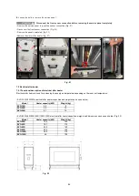
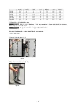
Page 95: ...ect the sensor connection before removing the electrical heater Fig 77 Reset function RISK OF INJURY Make sure that the power connection is disconnected and fan is not moving before doing any work on the device Danger of electric shock moving parts fan and hot surface Wait for 3 minutes before doing maintenance The manual RESET takes place by pressing the reset lever which is located directly on t...

Page 96: ...preheater will be disconnected from the power supply When the temperature falls below 70o C the electrical heater will automatically switch on 7 4 Outdoor air pre filter ePm10 50 7 4 1 Functional description of outdoor air pre filter The ePm10 50 is pre filter It is used to prevent the contamination on the fine filter 7 4 2 Installation of outdoor air pre filter RISK OF INJURY Make sure that the p...

Page 97: ... damper Recirculation damper module dimensions and weight can be seen below Fig 81 A mm B mm C mm D mm E mm F mm Weight kg EVO 50R 1625 155 1470 1240 100 480 85 EVO 60R 1745 155 1590 1360 100 480 100 EVO 80R 1995 155 1840 1610 100 480 130 EVO 95R 2095 155 1940 1710 100 480 150 EVO 120R 2245 155 2090 1860 100 480 190 EVO 150R 2495 155 2340 2110 100 480 230 7 5 2 Installation of recirculation damper...

Page 98: ...e connecting cables to the rotor module pull the cable from the cable duct to a sufficient length Fig 84 4 Fasten the cables with cable tie and plug the electrical connections Fig 85 Fig 85 Fig 83 Recirculation module Fig 84 Recirculation module Rotor module ...

Page 99: ...amper 7 6 1 Functional description of outdoor damper The outdoor exhaust dampers prevent the air entering into the device when the device is not operating Outdoor dampers open 30 seconds before the fan operates automatically The outdoor and exhaust air dampers are connected to one digital output Outdoor exhaust dampers have tightness class 2 Outdoor exhaust damper dimensions and weights can be see...

Page 100: ... EVO 95R 8 6 EVO 120R 10 EVO 150R 13 7 6 2 Installation of outdoor damper Make sure that the power connection is disconnected before doing any work on the device Before the damper installation remove the filter and fan Install the damper before positioning the unit for easy access from both service side After install the accessory refer to chapter 4 1 for the commissioning 1 Unlock the lock and tu...

Page 101: ...eet metal part shown below and connect the bolts Fig 92 5 Plug the damper electrical connections Fig 93 7 6 3 Service and maintenance of outdoor damper The outdoor dampers and actuators must be regularly checked for contamination every 6 months Fig 92 Fig 91 Fig 93 ...

Page 102: ...ion temperature 6 C Condensation temperature 46 C Super heating 5 C Sub cooling 3 C Model Cooling capacity kW Weight kg EVO 15R 5 9 150 EVO 20R 9 1 165 EVO 30R 11 9 180 EVO 50R 20 1 210 EVO 60R 25 225 EVO 80R 36 8 250 EVO 95R 43 3 265 EVO 120R 62 5 270 EVO 150R 70 290 DX cooling coil module dimensions can be seen below Fig 94 A mm B mm C mm D mm E mm F mm G mm K mm EVO 15R 500 350 1000 675 155 100...

Page 103: ...nstall the accessory refer to chapter 4 1 for the commissioning Assembly area Observe the following criteria during installation to ensure that the module service is comfortable Fig 95 A is the minimum distance for servicing the cooling coil 1 Apply sealing strip to the surface where the module will be connected with the device Fig 96 Fig 95 MODEL A mm EVO 15R 960 EVO 20R 1060 EVO 30R 1170 EVO 50R...

Page 104: ...If the cooling module is to be connected directly to the device connect the device connector and the cooling module connector each other Fig 97 b If the DX cooling module is to be connected after the electrical water heater use the connection cable shown below to connect the heater module connector and the cooler module connector each other Fig 98 3 Tighten the bolt Fig 99 Fig 97 Fig 99 Unit suppl...

Page 105: ...ng before doing any work on the device It is recommended to clean condensate tray every 6 months 1 Unlock the lock and turn the handles counter clock wise direction for opening doors Fig 101 2 Clean condensate tray with a cloth Fig 102 It is recommended to check the DX coil for contamination every 6 months The DX coil must be inspected regularly for dirt and dust deposits If there are dirt and dus...

Page 106: ...oil is not damaged neither mechanically nor chemically Allow DX coil to dry before installation 1 Remove the sheet metal parts Fig 103 2 Remove the service panel carefully Fig 104 3 Remove the DX coil carefully Fig 105 Fig 103 Fig 104 Fig 105 ...

Page 107: ... 6 kW 150 EVO 20R 9 5 kW 165 EVO 30R 12 9 kW 180 EVO 50R 19 2 kW 210 EVO 60R 23 8 kW 225 EVO 80R 38 8 kW 250 EVO 95R 46 5 kW 265 EVO 120R 60 8 kW 270 EVO 150R 69 3 kW 290 Cooling coil water module dimensions can be seen below Fig 106 A mm B mm C mm D mm E mm F mm G mm K mm Coil inlet outlet pipe diameter inch EVO 15R 500 350 1000 675 155 100 820 760 1 2 EVO 20R 500 350 1000 735 155 100 920 860 3 4...

Page 108: ... doing any work on the device Cooling coil inlet outlet pipes should be insulated Refer to the electrical diagrams for cooling coil signal connections Danger of electric shock moving parts fan and hot surfaces After install the accessory refer to chapter 4 1 for the commissioning 1 Apply sealing strip to the surface where the module will be connected with the device Fig 108 Fig 108 Fig 107 MODEL A...

Page 109: ... or heating module If the cooling module is to be connected directly to the device connect the device connector and the cooling module connector each other Fig 109 b If the water cooling module is to be connected after the electrical water heater use the connection cable shown below to connect the heater module connector and the cooler module connector each other Fig 110 3 Tighten the bolt Fig 111...

Page 110: ...n is not moving before doing any work on the device It is recommended to clean condensate tray every 6 months 1 Unlock the lock and turn the handles counter clock wise direction for opening doors Fig 113 2 Clean condensate tray with a cloth Fig 114 It is recommended to check the cooling coil for soiling every 6 months The cooling coil must be inspected regularly for dirt and dust deposits If there...

Page 111: ...he cooling coil is not damaged neither mechanically nor chemically Allow cooling coil to dry before installation 1 Remove the sheet metal parts Fig 115 2 Remove the service panel carefully Fig 116 3 Remove the coil carefully Fig 117 Fig 115 Fig 116 Fig 117 ...

Page 112: ...it weather roof EVO 15R 20R 30R Fig 119 Dividable unit weather roof EVO 50R 60R 80R 95R 120R 150R Fig 120 Dividable unit weather roof with recirculation damper EVO 50R 60R 80R 95R 120R 150R Fig 121 Fig 118 Non dividable unit weather roof A mm B mm C mm D mm E mm EVO 15R 910 760 230 1700 1800 EVO 20R 1010 860 240 1700 1800 EVO 30R 1120 970 240 1700 1800 Fig 119 Dividable unit weather roof A mm B mm...

Page 113: ...ving before doing any work on the device Make sure that the weather roof inclination is in the service direction for easy service to terminal box 7 8 2 1 Installation of EVO 15R 20R 30R weather roof 1 Make sure that the unit modules are assembled correctly 2 Apply the gasket on the top of the unit Fig 122 Fig 122 Gasket Dividable unit weather roof with recirculation damper A mm B mm C mm D mm E mm...

Page 114: ...ame level with the unit s vertical panels Fig 123 4 Place the weather roof top sheets to top of the assembly and screw in the opened holes Fig 124 5 Place weather roof sealing pieces on the assembly and screw in the holes that as shown Fig 120 Aling With Panel Fig 123 Fig 124 Fig 125 ...

Page 115: ... weather roof 1 Make sure that the unit modules are assembled correctly 2 Apply the gasket on the top of the unit Fig 127 3 Place the weather roof base frames according to the labels Fig 128 4 Fix the weather roof base frames to each other using bolts Fig 129 Fig 126 Fig 129 Fig 127 Module 1 Module 2 Module 3 Fig 128 ...

Page 116: ...same level with the unit s vertical panels Fig 130 6 Mount the weather roof assembly to unit with screws from the all holes that as shown Fig 131 7 Place the weather roof top sheets to top of the assembly and screw in the opened holes Fig 132 Aling With Panel Fig 130 Fig 131 Fig 132 ...

Page 117: ...117 8 Apply the silicone to edge of the electrical box and connection areas Fig 133 9 Place weather roof sealing pieces on the assembly and screw in the holes that as shown Fig 134 Fig 133 Fig 134 ...

Page 118: ...odule is to be installed the outdoors it is necessary to use a weather roof Weather roof protects the module against weather conditions such as rain and snow Weather roof delivery includes all sheet metal parts sealing screws and silicone DX water cooling module weather roof dimensions can be seen below Fig 136 Electrical water after heating module weather roof dimensions can be seen below Fig 137...

Page 119: ... IP Class with weather roof EVO 50R 10 IP 54 EVO 60R 13 IP 54 EVO 80R 16 IP 54 EVO 95R 17 IP 54 EVO 120R 19 IP 54 EVO 150R 21 IP 54 7 10 2 Installation of module weather roof RISK OF INJURY Make sure that the power connection is disconnected and fan is not moving before doing any work on the device Apply the gasket on the top of the module Fig 138 Place the weather roof on the module and screw 4 8...

Page 120: ...information about adapters rectangular to round Please refer to chapter 7 14 for more information about flexible connectors Outdoor and exhaust spigot dimensions and weights can be seen below Outdoor spigot Fig 140 A mm B mm C mm Weight kg EVO 15R 410 370 530 17 EVO 20R 530 370 530 19 EVO 30R 640 430 530 20 EVO 50R 915 530 530 25 EVO 60R 915 530 530 25 EVO 80R 1115 530 530 28 EVO 95R 1260 530 530 ...

Page 121: ... 2 Connect the spigot to the device from the corners with M8x16 bolts Fig 143 In EVO 30R 50R 60R 80R 95R 120R 150R models after connection the bolts attach to the clamp shown below to fixing the spigot refer to chapter 2 1 4 for more information about clamp holes quantity 7 11 3 Service and maintenance of outdoor exhaust air spigot It is recommended to check the spigots for damage every 6 months O...

Page 122: ...ature C 0 50 0 50 0 50 0 50 0 50 0 50 0 50 0 50 0 50 Ambient Temperature with e box heater C 20 50 20 40 20 50 20 50 20 40 20 50 20 50 20 40 20 40 7 12 2 Installation of e box heater RISK OF INJURY Make sure that the power connection is disconnected and fan is not moving before doing any work on the device Danger of electric shock After install the accessory refer to chapter 4 1 for the commission...

Page 123: ...is to be connected to the device the adapter rectangular to round duct must be used 7 13 2 Installation of adapter rectangular round RISK OF INJURY Make sure that the power connection is disconnected and fan is not moving before doing any work on the device Make sure that a gasket is applied between the adapter and the device Fig 156 Connect the adapter to the outlets of the device with the M8X16 ...

Page 124: ...esentative locations on inner air duct surface for contamination corrosion and condensation every 12 months Check accessible air duct sections for damage every 12 months 7 15 CAP modus Pressure transmitter 7 15 1 Functional description of CAP modus This mode is used for controlling fans with constant air pressure in air duct via pressure transmitter If constant pressure is selected the duct pressu...

Page 125: ...tween the CO2 sensor and device electrical box refer chapter 8 for electrical connections 7 18 VOC room sensors 7 18 1 Functional description of VOC room sensors VOC sensors measure the amount of organic compounds that are vapor at room temperature in the room or environment 7 18 2 Installation of VOC room sensors Make sure that the power connection is disconnected before doing any work on the dev...

Page 126: ...to sensors 2 Make the electrical connections between the signal converter and device electrical box refer chapter 8 for electrical connections 7 21 Siphon for cooling module 7 21 1 Functional description of siphon To ensure the constant water flow not to allow too much air to enter the drainage and to prevent water entering into the system the condensate outlets should be used with siphon Existing...

Page 127: ...127 7 21 3 Service and maintenance of siphon It is recommended to check the siphon pipes for any contamination and damage every 6 months ...

Page 128: ...128 CHAPTER 8 WIRING DIAGRAM OVERVIEW 8 0 EVO 15R wiring diagram EVO 15R unit wiring diagram Fig 169 EVO 15R control panel wiring diagram Fig 170 EVO 15R accessories wiring diagram Fig 171 Fig 169 ...

Page 129: ...129 Fig 170 Fig 171 ...

Page 130: ...130 Fig 171 ...

Page 131: ...131 8 1 EVO 20R wiring diagram EVO 20R unit wiring diagram Fig 172 EVO 20R control panel wiring diagram Fig 173 EVO 20R accessories wiring diagram Fig 174 Fig 172 ...

Page 132: ...132 Fig 173 Fig 174 ...

Page 133: ...133 Fig 174 ...

Page 134: ...134 8 2 EVO 30R wiring diagram EVO 30R unit wiring diagram Fig 175 EVO 30R control panel wiring diagram Fig 176 EVO 30R accessories wiring diagram Fig 177 Fig 175 ...

Page 135: ...135 Fig 176 Fig 177 ...

Page 136: ...136 Fig 177 ...

Page 137: ...137 8 3 EVO 50R wiring diagram EVO 50R unit wiring diagram Fig 178 EVO 50R control panel wiring diagram Fig 179 EVO 50R accessories wiring diagram Fig 180 Fig 178 ...

Page 138: ...138 Fig 179 Fig 180 ...

Page 139: ...139 Fig 180 ...

Page 140: ...140 8 4 EVO 60R wiring diagram EVO 60R unit wiring diagram Fig 181 EVO 60R control panel wiring diagram Fig 182 EVO 60R accessories wiring diagram Fig 183 Fig 181 ...

Page 141: ...141 Fig 182 Fig 183 ...

Page 142: ...142 Fig 183 ...

Page 143: ...143 8 5 EVO 80R wiring diagram EVO 80R unit wiring diagram Fig 184 EVO 80R control panel wiring diagram Fig 185 EVO 80R accessories wiring diagram Fig 186 Fig 184 ...

Page 144: ...144 Fig 185 Fig 186 ...

Page 145: ...145 Fig 186 ...

Page 146: ...146 8 6 EVO 95R wiring diagram EVO 95R unit wiring diagram Fig 187 EVO 95R control panel wiring diagram Fig 188 EVO 95R accessories wiring diagram Fig 189 Fig 187 ...

Page 147: ...147 Fig 188 Fig 189 ...

Page 148: ...148 Fig 189 ...

Page 149: ...149 8 7 EVO 120R wiring diagram EVO 120R unit wiring diagram Fig 190 EVO 120R control panel wiring diagram Fig 191 EVO 120R accessories wiring diagram Fig 192 Fig 190 ...

Page 150: ...150 Fig 191 Fig 192 ...

Page 151: ...151 Fig 192 ...

Page 152: ...152 8 8 EVO 150R wiring diagram EVO 150R unit wiring diagram Fig 193 EVO 150R control panel wiring diagram Fig 194 EVO 150R accessories wiring diagram Fig 195 Fig 193 ...

Page 153: ...153 Fig 194 Fig 195 ...

Page 154: ...154 Fig 195 ...

Page 155: ...155 ...

Reviews: