background image

SN

10

p

lu

s

lo

n

g

si

d

e

Assembly

www.aerocompact.com

17

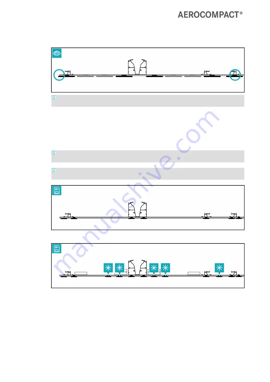
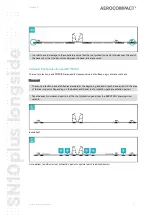
In order to avoid damage to the substrate, ensure that the roof protection pad protrudes over the end of
the base rail or that the transitions between the base rails are covered.

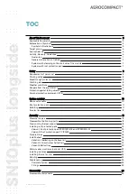
Version 2: Roof protection pad PP 150/80

The roof protection pads PP150/80 are used for less sensitive roof surfaces, e.g. concrete roofs, etc.

Placement

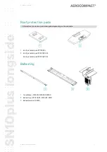
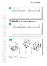
The roof protection pads are fitted as standard at the beginning and end of each base rail and in the area
of the rear supports. Depending on the ballast, additional roof protection pads are installed per rail.

Take the exact number and position of the roof protection pads from the AEROTOOL planning doc-
uments.

less ballast

more ballast / additional roof protection pads for optimal point load distribution

+

+

+

+

+

+

+

+

+

+

+

+

+

+

+

+

+

+

+

+

+

+

+

+

+

+

+

+

+

+

+

+

+

+

+

+

+

+

+

+

+

+

+

+

+

+

+

+

+

+

+
+

+

+

+

+

+

+

+
+

+
+
+
+

+
+
+

+

+
+

+

+

+

+

+

+

+

+

+

+

+

+

+

+

+

+

+

+

+

+

+

+

+

+

+

+

+

+

+

+

+

+

+

+

+

+

+

+

+

+

+

+

+

+

+

+

+

+

+

+

+

+

+

+

+

+

+

+

+

+

+

+

+

+

+

+

+

+

+

+

+

+

+

+

+

+

+

+

+

+

+

+

+

+

+

+

+

+

+

+

+

+

+

+

+

+

+

+

+

+

+

+

+

+

+

+

+

+

+

+

+

+

+

+

+

+

+

+

+

+

+

+

+

+

+

+

+

+

+

+

+

+

+

+

+

+

+

+

+

+

+

+

+

+

+

+

+

+

+

+

+

+

+

+

+

+

+

+

+

+

+

+

+

+

+

+

+

+

+

+

+

+

+

+

+

+

+

+

+

+

+

+

Summary of Contents for CompactFLAT SN10plus

Page 1: ...CompactFLAT SN10plus longside Assembly Instructions Version 02 2021 Language English Original language German Original installation instructions Important Read carefully before installation...

Page 2: ...erman Any assembly instructions in another lan guage are a translation of the assembly instructions in German The assembly instructions are protected by copyright Without written permission from AEROC...

Page 3: ...objects 9 Personal protective equipment PPE 9 System overview 10 Basic components 10 Roof protection pads 11 Ballasting 11 Accessories 12 Assembly 13 Measure the area 13 Preassemble the front supports...

Page 4: ...SN10plus longside www aerocompact com 4 Dismantle clamps 26...

Page 5: ...structions symbols terms and abbreviations are used The following symbols indicate notes which are not relevant to safety but which make working with the assembly instructions easier Requirements for...

Page 6: ...PV modules Any other use of the CompactFLAT system is considered improper Liability Warranty Guarantee These assembly instructions and the project report supplied with the product are integral parts...

Page 7: ...he corresponding fasteners on the respective roof in terms of warranties nor for the professional execution Errors and damage as well as limited or insufficient functionality of the system due to inco...

Page 8: ...ement roofs can be prone to breakthrough over the entire surface Define walking routes and secure them with load distribution measures On roofing or roof structures that do not have sufficient load be...

Page 9: ...roof on which work is being carried out must be protected from any falling objects Where this does not succeed affected areas must be closed to the public Persons involved in the construction project...

Page 10: ...m overview www aerocompact com 10 SYSTEM OVERVIEW Basic components 1 End clamp CLE10 2 Back support SN10 SN10F 3 Torx screw M8x16 A2 70 701 507 4 Base rail BR2390 5 Starting piece base rail BR130 6 Fr...

Page 11: ...fferent roof protection pads are supplied depending on the substrate 1 Roof protection pad PP 150 80 2 Roof protection pad PP 250 120 CL Roof protection pad PP 200 120 CL Ballasting 1 Cross brace CS18...

Page 12: ...System overview www aerocompact com 12 Accessories 1 Angle connection to mechanical attachment AC200 AC80 2 Wire clamp for bonding WCL8 10 3 Aluminium wire round 8 mm for bonding AWR8 4 Cable tie cli...

Page 13: ...from the planning documents Measure the length of the module field and mark the line Measure the width of the module field and mark the line Determine the distance between the module rows according t...

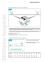
Page 14: ...front mark of the front support Place base rails and front support Hand tighten the screws Tighten the screws to 10 Nm or 7 38 ftlb with a torque wrench Premounting the rear support 1 determine the di...

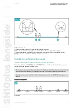
Page 15: ...lling roof protection pads Version 1 Roof protection pad PP 200 120 CL and PP 250 120 CL The roof protection pads PP 200 120 CL and PP 250 120 CL are used for sensitive roof surfaces e g mem branes bi...

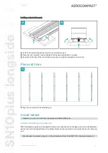
Page 16: ...less ballast more ballast additional roof protection pads for optimal point load distribution Installing roof protection pads Place the roof protection pads so that the clip is facing upwards with the...

Page 17: ...ds PP150 80 are used for less sensitive roof surfaces e g concrete roofs etc Placement The roof protection pads are fitted as standard at the beginning and end of each base rail and in the area of the...

Page 18: ...ile Place rail lines Align the rail lines with the selected grid Install ballast Depending on the circumstances the system is ballasted differently Variation 1 Ballasting on the base rail With this ba...

Page 19: ...the wings of the ballast clamp are flush with the ballast blocks Place the ballast blocks Variant 2 Cross struts as ballast rail The ballast rails can be mounted in the following positions behind the...

Page 20: ...ks according to Aerotool planning documents Variant 3 Ballast tray The ballast trays can be mounted in the following positions behind the first front support under module in front of the first back su...

Page 21: ...y s centre hole on the right and left on the penultimate support For a reliable compound 2 ballast trays overlap halfway Attach the ballast tray so that it can be bolted to 2 3 base rails Hand tighten...

Page 22: ...Microinverter montieren optional USA In the SN10 plus systems the microinverter is pre mounted on the modules Install the microinverter on the module according to the module manufacturer s instructio...

Page 23: ...module on the supports Place the module flush with the clamps The distance A between the modules is 2 cm As an aid 2 clamps can be used as gauges Attach an end clamp to the back upright Continue plac...

Page 24: ...completely Installing the roof anchor Take the number and positions of the mechanical attachments from the AEROTOOL planning doc uments Mount the angle connection to the mechanical attachment on a re...

Page 25: ...egularly by qualified per sonnel The operator of the equipment must perform the following maintenance items once a year A test of the system is necessary after severe weather events e g wind storm sno...

Page 26: ...pact com 26 DISASSEMBLY Disassemble components Disassembling the system Carry out the assembly steps in reverse order Dismantle clamps Completely unscrew the screw on the clamp If clamps are re instal...

Reviews: