background image

Fokker


Dr.1


46.7”


1/6


Scale


Page


5


Copyright©


2007

11


M.K.


Bengtson


All


Rights


Reserved


Rev


07/11


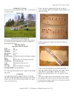
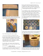
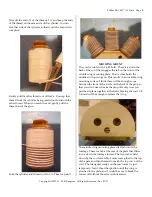
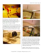
Apply


glue


to


the


frames,


and


lay


the


sheeting


down


on


top


of


the


frame.


Pin


it


down


at


the


center


first,


and


then


work


out


to


the


ends


of


the


sheeting.


Let


dry.


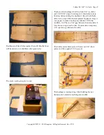
Now


finish


sheeting


with


the


other


two


pieces.


A


note


on


choice


of


glue


when


using


thin


ply.


Thin


plywood


soaks


up


CA


glues


like


a


sponge.


Once


the


glue


hardens,


it


makes


the


ply


very


hard


to


sand.


You


will


wind


up


with


uneven


sanding


between


areas


hardened


by


glue


and


those


that


are


not.


For


that


reason,


I


suggest


using


aliphatic


glues.


Takes


a


while


longer


to


dry,


but


it


will


be


much


easier


to


sand


and


finish.


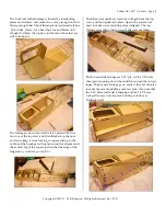
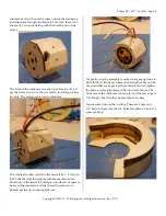
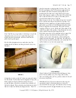
The


front


of


the


cowl


is


formed


with


1/4

ʺ 

balsa


sheet


pieces,


and


then


the


cowl


is


carved


and


sanded


to


shape.


I

ʹ

ll


do


that


later.


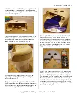
DUMMY


MOTOR


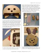
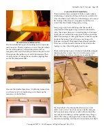
The


Axi


motor


mount


is


part


of


the


dummy


rotary


engine.


It

ʹ

s


quite


the


piece


of


work.


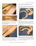
The


dummy


crankcase


is


composed


of


layers


of


laser


cut


1/16

ʺ 

ply,


1/8

ʺ 

lite


ply,


1/8

ʺ 

balsa,


and


1/4

ʺ 

balsa.


Each


part


has


3


holes


laser


cut


through


which


motor


mounting


bolts


will


pass.


When


gluing


the


parts


together,


pay


attention


and


make


sure


these


holes


are


always


aligned.


Also,


assemble


the


pieces


so


that


the


grain


alternates


for


added


strength.


Now


I


suggest


you


count,


count,


and


recount


how


many


layers


of


1/4

ʺ 

balsa


it


takes


to


make


the


crankcase.


You


will


find


it


takes


6.


Notice


that


there


are


8


pieces


supplied.


Take


two


of


them


and


put


them


out


of


reach,


so


you


will


not


be


stupid


enough


to


use


all


8


and


wind


up


with


a


crankcase


that


is


too


long.


Should


that


happen,


you


can


use


a


razor


saw


and


remove


the


offending


piece.


Should


you


still


not


be


able


to


count,


you


can


reach


for


the


razor


saw


and


repeat.


Study


the


plan


and


make


sure


the


pieces


are


assembled


in


the


correct


order.


Note


that


there


is


a


1/8

ʺ 

balsa


piece


in


the


middle


with


extra


notches.


These


are


for


the


dummy


cylinder


construction


later.


The


plans


say


to


make


a


channel


to


pass


the


motor


wires


through,


out


the


back


of


the


crankcase.


This


is


certainly


do

able,


but


I


decided


to


make


a


hole


at


the


top


of


the


Summary of Contents for Fokker Dr.1 46.7"

Page 1: ... All Rights Reserved Rev 07 11 Fokker Dr 1 46 7 1 6 Scale R C Scale Model Instructions CONTACT INFORMATION Designed by M K Bengtson Prototype by Frank Jaerschky Manufactured and Distributed by Bengtson Company e mail sales aerodromerc com www aerodromerc com ...

Page 2: ...Builder Frank Jaerschky The following is taken from Frankʹs comments in building the model FUSELAGE Assembly starts by gluing together the two 3 16ʺ parts that make the left and right forward fuselage sides There are precut slots and holes for bolts and formers so make sure you open them up I like to use yellow aliphatic glue It gives me time to correct mistakes Makes for a slightly longer build t...

Page 3: ... should have done this step before adding the doublers I like to build both sides one on top of the other separated by plastic wrap or wax paper to make sure they are identical With the doublers I will have a 1 16ʺ gap between the balsa sides if I lay them on top of each other Iʹll just make a temporary 1 16ʺ spacer to go between the sides The rudder assembles easily with laser cut 3 16ʺ sheet pie...

Page 4: ...A square slid up to the outline of the fuselage on the plan is used for alignment If the vertical leg of the square just touches the edge of the longerons you know youʹre ʺOnʺ The balsa cross members were cut to length from the top view and then glued into place Again the square was used to make sure everything stayed aligned The top formers were then glued on top of the cross members The forward ...

Page 5: ...ames and spacers Larger frame on the right is the rear of the cowl and actually forms part of the middle upper wing retention system COWL The ply sheeting is supplied in 3 pieces Instead of butt gluing the sheeting I sanded a bevel on the sheets where the join so that they could overlap a bit and form a scarf joint Once sanded this will be a bit stronger and cleaner than a butt joint Start with th...

Page 6: ...of laser cut 1 16ʺ ply 1 8ʺ lite ply 1 8ʺ balsa and 1 4ʺ balsa Each part has 3 holes laser cut through which motor mounting bolts will pass When gluing the parts together pay attention and make sure these holes are always aligned Also assemble the pieces so that the grain alternates for added strength Now I suggest you count count and recount how many layers of 1 4ʺ balsa it takes to make the cran...

Page 7: ...inch 4 40 bolts that run through the crankcase and bolt into blind nuts in the firewall Small plywood laser cut spacers between the crankcase and the firewall not shown in photos set the down and right thrust Iʹm pretty sure the assembly is quite strong enough as it is But I think I will line each hole with a length of brass tube Iʹm afraid that I may get a bit ham fisted and over tighten the bolt...

Page 8: ... blind nuts into place Iʹve started on the included dummy motor cylinders The crankcase has already been described earlier in this thread The cylinders are made up of a piece of 1 8ʺ sq balsa and some other laser cut balsa disks The disks are glued to the square piece and then the supplied pre printed card stock is wrapped around that assembly and glued in place Then the cylinder is glued to the c...

Page 9: ...oes quite quickly too In case youʹre curious each cylinder took about 42ʺ of thread so thatʹs 9X42ʺ 31 5 feet total Luckily you can reuse the ʺspacerʺ thread if youʹre careful Put a small drop of thick CA on the cylinder Lay both threads in the glue and let harden Trim both ends of the threads Start wrapping the threads around the cylinder Make sure the threads stay parallel and do not cross each ...

Page 10: ... wing mounting plate That is what holds the middle and top wings on This results in an invisible wing mounting system I think there will be enough room between the front of the cowl and the back of the prop so that you donʹt need to take the prop off every time you put the airplane together at the field Moving the cowl 1 4ʺ forward will be enough to release the wing The middle wing mounting plate ...

Page 11: ...ymore There is not enough clearance between the front face of the cowl and the motor shaft to allow the cowl to go on and off So the designer and I scratched our heads about this for a while In the end we decided it would probably be best to have a slot in the lower cowl lip underneath the prop shaft hole To hide the hole I cut a wedge out of the cowl and used magnets to hold the wedge in place My...

Page 12: ...g out Once the cowl is painted I think the part line will be very hard to see especially as the cowl will be black Just a couple of shots of the cowl and primer Picture 1 shows the cowl with 1 coat of primer applied I use Motomaster brand ʺPrimer Scratch Fillerʺ available at Canadian Tire If you arenʹt Canadian Canadian Tire is like a Menʹs dream department store with loads of cool guy stuff and e...

Page 13: ...es The main spars are 3 16 X1 2 balsa The trailing edges are laser cut 1 32 ply with the TE scallops laser cut The distinctive Dr1 ʺSaw Toothʺ leading edge is laser cut from 1 32 ply There are laser cut 3 16ʺ pieces that go on top of the forward main spar between the ribs So when adding the ribs itʹs merely a process of working from one end to the other adding a block a rib a block etc The ply LE ...

Page 14: ...se tubes Although Iʹm thinking of maybe using carbon fiber tubes to save some weight Middle wing is attached to mounting plate with 4 40 bolts and blind nuts installed in mid wing Tab at rear of mounting plate fits into slot in fuselage just forward of the cockpit Slot in rear of cowl goes over the tab at the front of the mid wing mounting plate Cowling is secured with 2 4 40 bolts and blind nuts ...

Page 15: ...ap balsa from some of the laser cut part sheets that is perfect for the job To make sure everything will look good when Iʹm done I put the wing in position on the fuselage and put some plastic wrap between the fuselage and the back of the middle wing to make sure they didnʹt become permanently attached With some trial and error I cut a piece of balsa as wide as I could so that it would sit on top ...

Page 16: ...ouch the iron to the assembly let it get good and hot and let the solder flow into the joint The final result is tough as nails I worked on the cabane struts this afternoon They are made from 3 32ʺ music wire The top wing is attached to the cabanes with 1 8ʺ nylon landing gear straps and 4 40 bolts The bottom of the front struts slide into a 1 8ʺOD piece of brass tubing that is built into the midd...

Page 17: ...op wing in a rib also made out of 2 1 16ʺ ply and 1 1 32 ply pieces I must admit I cheated with the struts It is absolutely essential that all 4 pieces of the cabane struts be the correct length and have all the correct angles Because of this I felt I would have trouble making my bends accurately enough to do the job So after roughly bending and sizing each strut I cut it in half and then chopped ...

Page 18: ...in place A thin bead of CA around the rim makes for a secure tire Paper cones are cut out Use a ball point pen to score each line on the back to make an impression of spokes It is helpful to do this operation on a paper tablet so that the pen makes a good crease Fold the paper along the crease lines to exaggerate the raised lines One of the sections forming a wedge is cut out Make cuts to the cent...

Page 19: ...dered to the axle I then epoxied the tabs to the base The brass has just enough flex to allow a little wiggle I sheeted the top with 1 16ʺ balsa I also made the holes a little over sized in the top sheeting where the wire passes through If the sheeting is right up against the wire any wiggle will crack the sheeting WING SERVOS Hereʹs the aileron servo installation I chose the lazy man method and u...

Page 20: ... edge should look great when the wings are covered and painted And hey the wingtips came out with minimal wrinkles I have started covering the fuselage I was worried about this as there are a few tricky areas namely the area between the lower wing root and the fuselage side It actually came out very well I think Iʹm starting to think I can make Polyspan do anything Just look at the sexy curves it ...

Page 21: ...d around the wire strut This should make things pretty strong I am going to do the front fairing after the model is completed and the upper wing is joined to the middle wing I hate hate hate servo wires flopping in the breeze So my plan is to attach the wings to each other glued the balsa front fairings on then glue the servo wires along the inside of the fairing Then Iʹll wrap everything with Pol...

Page 22: ...t balsa in the form of a side and front profile of a pilot The plan sheet says ʺʺGlue together fill with foam and paintʺ Heck if itʹs that easy I might as well give it a try Iʹm using blue foam as it seems to be much easier to carve with a hobby knife and sandpaper than white bead foam Once I get the pilot to shape Iʹll probably give him some sort of paper mache finish and then add details like bu...

Page 23: ...d a fur collar for those cold missions over the front in pursuit of der Englander I used a pencil to mark out where I thought a fur collar would go Then I used a bead of spackle and a small spatula to get the shape I then used the end of a coarse bristled paint brush and stippled the spackle When itʹs dry and painted I think it will look good too I didnʹt think that Iʹd be putting this much work i...

Page 24: ...ts The battery slides in through the forward most hatch and the top of the pack is retained by the ʺLʺ the shelf will also serve as a place to mount the ESC and RX The bottom of the battery rest on the forward landing gear mount I then glued a piece of 1 8ʺ basswood to the inside of the hatch Once the hatch is in place the basswood piece stops the battery from sliding backwards Itʹs simple and see...

Page 25: ... 6 minutes so up we go again This time I advanced the power more rapidly and it leapt off the ground in no time and pointed her nose up and kept on climbing The next 2 landings ended in nose overs I landed too fast and when the triplane starts bouncing down the runway on the roll out it will eventually find the right bump that flips her on to the nose No damage at all thought The next 5 landings I...

Reviews: