MAINTENANCE MANUAL
IFR 4000
2-2-3
Page 59
Aug 1/04
(2) Miscellaneous
PREREQUISITES:
Test Setup (para 2-2-3F(1)
TEST EQUIPMENT:
Measuring
Receiver
Signal Generator
Audio
Analyzer
Power
Meter
TNC Precision Short (Male)
RF Amplifier (100 W)
20 dB Directional Coupler (N-Type Connector)
20 dB N-Connector Attenuator
250 MHz Low-Pass Filter (N-Type Connector)
10 dB BNC Connector Attenuator
3 dB, 100 W N-Type Connector Attenuator
STEP PROCEDURE
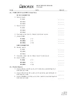
1. From the Calibration Screen, press the MISC CALS Soft Key to enter the MISC
CALS Screen.
TXCO
2. Press the TCXO Soft Key to display the TCXO CAL Sequence Screen.
3. Connect the Signal Generator to the AUX I/O Connector. Set the Signal
Generator for 10.000 MHz, +6 dBm output and no modulation. (The Signal
Generator should have a frequency error of <0.1 PPM.)
4. Press the START Soft Key to begin the TCXO CAL Sequence.
5. When the TCXO CAL Sequence is complete, press the SAVE & RETURN Soft
Key to return to the MISC CALS Screen.
6. Disconnect the Signal Generator.
SWR
7. Press the SWR Soft Key to display the SWR CAL Sequence Screen.
8. Connect TNC Short to the SWR Connector.
9. Press the NEXT Soft Key to begin the SWR CAL Sequence and follow the
on-screen prompts.
10. When the SWR CAL Sequence is complete, press the SAVE & RETURN Soft Key
to return to the MISC CALS Screen.
POWER METER
11. Press the POWER METER Soft Key to display the POWER METER CAL
Sequence Screen.
12. Connect Test Equipment to Test Set as shown in 2-2-3, Figure 5. Using the loss
figure recorded in 2-2-3F(1) Step 8, input that number as an offset in the Power
Meter and set the Power Meter to read Watts.
Summary of Contents for IFR 4000
Page 1: ...NAV COMM Test Set Maintenance Manual 1002 5600 4P0 IFR 4000...
Page 3: ...MAINTENANCE MANUAL IFR 4000 FOR QUALIFIED SERVICE PERSONNEL ONLY...
Page 4: ...MAINTENANCE MANUAL IFR 4000 THIS PAGE INTENTIONALLY LEFT BLANK...
Page 6: ...MAINTENANCE MANUAL IFR 4000 THIS PAGE INTENTIONALLY LEFT BLANK...
Page 12: ...MAINTENANCE MANUAL IFR 4000 INTRODUCTION Page 2 Aug 1 04 THIS PAGE INTENTIONALLY LEFT BLANK...
Page 32: ...MAINTENANCE MANUAL IFR 4000 2 2 1 Page 14 Aug 1 04 THIS PAGE INTENTIONALLY LEFT BLANK...
Page 34: ...MAINTENANCE MANUAL IFR 4000 2 2 1 Page 16 Aug 1 04 THIS PAGE INTENTIONALLY LEFT BLANK...
Page 42: ...MAINTENANCE MANUAL IFR 4000 2 2 2 Page 8 Aug 1 04 THIS PAGE INTENTIONALLY LEFT BLANK...
Page 108: ...MAINTENANCE MANUAL IFR 4000 2 2 4 Page 2 Aug 1 04 THIS PAGE INTENTIONALLY LEFT BLANK...
Page 160: ...MAINTENANCE MANUAL IFR 4000 2 2 4 Page 54 Aug 1 04 THIS PAGE INTENTIONALLY LEFT BLANK...
Page 166: ...MAINTENANCE MANUAL IFR 4000 2 3 1 Page 6 Aug 1 04 STEP PROCEDURE 4 Remove the Fuse...
Page 186: ...MAINTENANCE MANUAL IFR 4000 APPENDIX B Page 2 Aug 1 04 THIS PAGE INTENTIONALLY LEFT BLANK...
Page 188: ...MAINTENANCE MANUAL IFR 4000 APPENDIX C Page 2 Aug 1 04 THIS PAGE INTENTIONALLY LEFT BLANK...
Page 200: ...MAINTENANCE MANUAL IFR 4000 APPENDIX D Page 12 Aug 1 04 THIS PAGE INTENTIONALLY LEFT BLANK...
Page 206: ...MAINTENANCE MANUAL IFR 4000 APPENDIX E Page 6 Aug 1 04 THIS PAGE INTENTIONALLY LEFT BLANK...

