MAINTENANCE MANUAL
IFR 4000
2-3-2
Page 2
Aug 1/04
C. Reassembly Procedures
(1) Battery
O
Reassembly should be performed in reverse sequence of disassembly.
O
Torque the five captive screws on the Battery Cover to 8 in/lbs.
(2) Fuse
O
Reassembly should be performed in reverse sequence of disassembly.
O
Torque the five captive screws on the Battery Cover to 8 in/lbs.
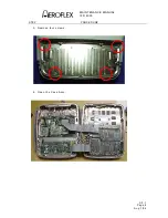
(3) Case
Assy
O
Reassembly should be performed in reverse sequence of disassembly.
O
Torque the eight screws on the Case Assy to 17 in/lbs.
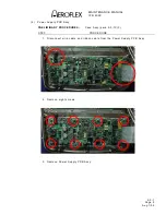
(4) Power Supply PCB A ssy
O
Reassembly should be performed in reverse sequence of disassembly.
O
Install new gap pad between the Power Supply PCB A ssy and the Chassis Assy.
O
Torque the eight screws on the Power Supply PCB A ssy to 6 in/lbs.
(5) RF
Assy
O
Reassembly should be performed in reverse sequence of disassembly.
O
Replace RF gasket if torn or damaged.
O
Torque the 11 screws on the RF Assy to 8 in/lbs.
O
Torque the two semi-rigid coaxial cable connectors to 10 in/lbs.
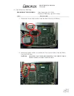
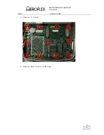
(6) Processor PCB Assy
O
Reassembly should be performed in reverse sequence of disassembly.
O
Torque the 4 nuts on the Processor PCB Assy to 3 in/lbs.
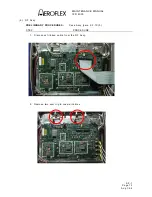
(7) Multi-Function PCB Assy
CAUTION
: EXERCISE CAUTION WHEN INSTALLING THE RIBBON CABLE FROM
THE LCD ASSY TO THE MULTI-FUNCTION PCB ASSY.
O
Reassembly should be performed in reverse sequence of disassembly.
O
Torque the 11 screws on the Multi-Function PCB Assy to 6 in/lbs.
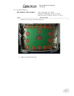
(8) Keypad PCB Assy
O
Reassembly should be performed in reverse sequence of disassembly.
O
Torque the 12 screws on the Keypad PCB Assy to 6 in/lbs.
O
Torque the five shell nuts on the Keypad PCB Assy to 6 in/lbs.
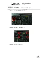
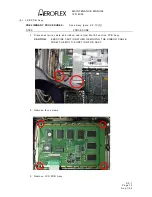
(9) LCD PCB Assy
O
Reassembly should be performed in reverse sequence of disassembly.
O
Reapply new double-stick tape.
O
Torque the four screws on the LCD PCB Assy to 6 in/lbs.
Summary of Contents for IFR 4000
Page 1: ...NAV COMM Test Set Maintenance Manual 1002 5600 4P0 IFR 4000...
Page 3: ...MAINTENANCE MANUAL IFR 4000 FOR QUALIFIED SERVICE PERSONNEL ONLY...
Page 4: ...MAINTENANCE MANUAL IFR 4000 THIS PAGE INTENTIONALLY LEFT BLANK...
Page 6: ...MAINTENANCE MANUAL IFR 4000 THIS PAGE INTENTIONALLY LEFT BLANK...
Page 12: ...MAINTENANCE MANUAL IFR 4000 INTRODUCTION Page 2 Aug 1 04 THIS PAGE INTENTIONALLY LEFT BLANK...
Page 32: ...MAINTENANCE MANUAL IFR 4000 2 2 1 Page 14 Aug 1 04 THIS PAGE INTENTIONALLY LEFT BLANK...
Page 34: ...MAINTENANCE MANUAL IFR 4000 2 2 1 Page 16 Aug 1 04 THIS PAGE INTENTIONALLY LEFT BLANK...
Page 42: ...MAINTENANCE MANUAL IFR 4000 2 2 2 Page 8 Aug 1 04 THIS PAGE INTENTIONALLY LEFT BLANK...
Page 108: ...MAINTENANCE MANUAL IFR 4000 2 2 4 Page 2 Aug 1 04 THIS PAGE INTENTIONALLY LEFT BLANK...
Page 160: ...MAINTENANCE MANUAL IFR 4000 2 2 4 Page 54 Aug 1 04 THIS PAGE INTENTIONALLY LEFT BLANK...
Page 166: ...MAINTENANCE MANUAL IFR 4000 2 3 1 Page 6 Aug 1 04 STEP PROCEDURE 4 Remove the Fuse...
Page 186: ...MAINTENANCE MANUAL IFR 4000 APPENDIX B Page 2 Aug 1 04 THIS PAGE INTENTIONALLY LEFT BLANK...
Page 188: ...MAINTENANCE MANUAL IFR 4000 APPENDIX C Page 2 Aug 1 04 THIS PAGE INTENTIONALLY LEFT BLANK...
Page 200: ...MAINTENANCE MANUAL IFR 4000 APPENDIX D Page 12 Aug 1 04 THIS PAGE INTENTIONALLY LEFT BLANK...
Page 206: ...MAINTENANCE MANUAL IFR 4000 APPENDIX E Page 6 Aug 1 04 THIS PAGE INTENTIONALLY LEFT BLANK...

