


MAINTENANCE MANUAL
IFR 4000
2-2-1
Page 1
Aug 1/04
SECTION 2 - TROUBLESHOOTING
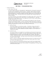
1. Theory of Operation
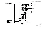
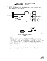
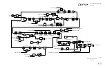
A. Power Supply PCB Assy
The Power Supply PCB Assy is responsible for supplying power to the internal modules for
operation and for charging the internal batteries. The Power Supply PCB A ssy operates
from externally supplied DC power and provides simultaneous run and battery charge, or
battery charge only. The battery charge time increases when in the run and charge mode.
The Power Supply Assy consists of a DC-DC Converter, ON/OFF Control circuitry and the
Battery Charger circuitry. The external DC input is supplied from an External DC Power
Supply (supplied).
The internal batteries are removable/replaceable Li Ion battery pa cks with an internal "gas-
gauge" feature that allows accurate determination of remaining battery life. Maximum
operating and storage temperature for Li Ion batteries is -20
°
C to +60
°
C and the maximum
charging temperature is 0
°
C to +45
°
C.
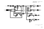
The Power Supply PCB Assy contains a synchronous buck converter to convert the input
voltage to a fixed output voltage (+10 Vdc). The Power Supply PCB A ssy also contains a
low-pass filter to reduce the amount of internal emissions. The Input Converter Assembly is
capable of providing enough output current to charge the battery at full current and run the
Test Set at the same time, as long as the input voltage is within range.
(1) Battery
Charger
The battery charger is a boost type converter. This battery charger monitors the
battery voltage and temperature to determine if the battery is capable of being
recharged, and if it is safe to attempt to recharge the battery. The battery must be at
least at a 9.2 V level and the temperature must be between 0
°
and 45
°
C before a
charge cycle initiates.
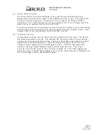
(2) Output
Circuitry
The output converters are comprised of a dual-phase synchronous buck converter for
deve3.3 and +5 V outputs. The converter also has an auxiliary output that is
used to ge16 V from the +VS source (either the battery or input converter). A
separate buck/boost converter is used to generate the -5 V output. The primary
converter provides dual phase control, as well as gate drive for the switching mosfets
and over-current protection. The main converter runs at 220 kHz, while the auxiliary
converter runs at 1.2 MHz.
Both +3.3 and +5 V outputs are capable of delivering up to 3 A of current and the 16 V
output can deliver up to 80 mA. If any of these three outputs experience a severe
over-current, the supply turns OFF.
The -5 V converter is a stand-alone buck/boost converter that runs at approximately
220 kHz and can deliver up to 400 mA of current before starting to fold back. If the
supply experiences a severe over-current condition, the supply stays in fold-back mode
until the short is removed.
Summary of Contents for IFR 4000
Page 1: ...NAV COMM Test Set Maintenance Manual 1002 5600 4P0 IFR 4000...
Page 3: ...MAINTENANCE MANUAL IFR 4000 FOR QUALIFIED SERVICE PERSONNEL ONLY...
Page 4: ...MAINTENANCE MANUAL IFR 4000 THIS PAGE INTENTIONALLY LEFT BLANK...
Page 6: ...MAINTENANCE MANUAL IFR 4000 THIS PAGE INTENTIONALLY LEFT BLANK...
Page 12: ...MAINTENANCE MANUAL IFR 4000 INTRODUCTION Page 2 Aug 1 04 THIS PAGE INTENTIONALLY LEFT BLANK...
Page 32: ...MAINTENANCE MANUAL IFR 4000 2 2 1 Page 14 Aug 1 04 THIS PAGE INTENTIONALLY LEFT BLANK...
Page 34: ...MAINTENANCE MANUAL IFR 4000 2 2 1 Page 16 Aug 1 04 THIS PAGE INTENTIONALLY LEFT BLANK...
Page 42: ...MAINTENANCE MANUAL IFR 4000 2 2 2 Page 8 Aug 1 04 THIS PAGE INTENTIONALLY LEFT BLANK...
Page 108: ...MAINTENANCE MANUAL IFR 4000 2 2 4 Page 2 Aug 1 04 THIS PAGE INTENTIONALLY LEFT BLANK...
Page 160: ...MAINTENANCE MANUAL IFR 4000 2 2 4 Page 54 Aug 1 04 THIS PAGE INTENTIONALLY LEFT BLANK...
Page 166: ...MAINTENANCE MANUAL IFR 4000 2 3 1 Page 6 Aug 1 04 STEP PROCEDURE 4 Remove the Fuse...
Page 186: ...MAINTENANCE MANUAL IFR 4000 APPENDIX B Page 2 Aug 1 04 THIS PAGE INTENTIONALLY LEFT BLANK...
Page 188: ...MAINTENANCE MANUAL IFR 4000 APPENDIX C Page 2 Aug 1 04 THIS PAGE INTENTIONALLY LEFT BLANK...
Page 200: ...MAINTENANCE MANUAL IFR 4000 APPENDIX D Page 12 Aug 1 04 THIS PAGE INTENTIONALLY LEFT BLANK...
Page 206: ...MAINTENANCE MANUAL IFR 4000 APPENDIX E Page 6 Aug 1 04 THIS PAGE INTENTIONALLY LEFT BLANK...


