


MAINTENANCE MANUAL
IFR 4000
2-2-1
Page 7
Aug 1/04
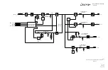
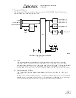
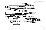
(5) Audio
Generator
The audio generation section of the Mult-Function PCB A ssy consists of three tone
generators.
AF Gen #1
AF Gen #1 synthesizer is followed by a 20 kHz LPF and a pair of attenuator DACs for
setting the modulation level. AF Gen #1 is used for 30 Hz variable in VOR mode,
90 Hz in LOC and G/S mode and one of the tone pairs in SELCAL mode. The two
attenuators are for LOC modulation level in dual mode and Main Path modulation level.
The attenuator DACs are 16 bit multipliers, followed by one channel of the OFFSET
DAC to remove the DC offset off the Audio signal. The data value written to the offset
channel of the OFFSET DAC is the same value written to the modulation attenuator,
except shifted right 8 places. Data is written to the offset channel every time the
modulation level or DDM is changed. For the Localizer channel, a data value of
65535 = 100% modulation. For the Main Path, a data value of 40960 is equivalent to
50% modulation (5/4 of the desired mod percent * 65535) due to attenuation by the
Master Mod Control.
AF Gen #1 serial control is shared with AF Gen #3, as well as all of the modulation
level attenuators. AF Gen #1 also shares AF1CLK (MCLK) (983.04 kHz) with AF Gen
#3 for all output tones.
AF Gen #2
AF Gen #2 synthesizer is identical to AF Gen #1 except AF Gen #2 has its own MCLK
signal (AF2_CLK) and serial bus. Functionally AF Gen #2 is used for 150 Hz in LOC or
G/S, 9960 for VOR and the second tone in SELCAL mode. The separate clock and
serial bus is for VOR mode, with the 30 Hz reference tone FM modulated on the 9960
audio tone. The lower 14 bits of the frequency word to AF Gen #2 at set at a 3 kHz
rate in VOR mode to generate the 30 Hz FM signal.
AF Gen #3
AF Gen #3 synthesizer is followed by a fixed 20 kHz Low-Pass Filter, a 12 bit
attenuator DAC for main path modulation and a fixed level output for Marker Beacon in
Tri-Mode operation. The attenuated output is routed to a switch controlled by the
AF3SW bit in the control register to select whether the tone is applied to the Main Path
modulation or to the Localizer path modulation.
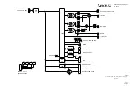
Master Mod Control
The Main Path modulation has an additional 12 bit attenuator in-line that changes the
combined modulation percentage of the summed tones. The calibrated position for the
Master Mod control is the 80% level. The Master Mod attenuator is followed by
another offset channel that is programmed to be the same value as the Master Mod
attenuator shifted 4 bits to the right.
Audio Synthesizer
The audio synthesizers have two frequency registers, two phase registers and a
control register for selection of the frequency register, phase register and output
options. The phase registers are set to zero to show the DAC output. The reset signal
(a bit in the control register) is used in all of the NAV modes to control the phase
relationship between AF Gen #1 and #2.
Summary of Contents for IFR 4000
Page 1: ...NAV COMM Test Set Maintenance Manual 1002 5600 4P0 IFR 4000...
Page 3: ...MAINTENANCE MANUAL IFR 4000 FOR QUALIFIED SERVICE PERSONNEL ONLY...
Page 4: ...MAINTENANCE MANUAL IFR 4000 THIS PAGE INTENTIONALLY LEFT BLANK...
Page 6: ...MAINTENANCE MANUAL IFR 4000 THIS PAGE INTENTIONALLY LEFT BLANK...
Page 12: ...MAINTENANCE MANUAL IFR 4000 INTRODUCTION Page 2 Aug 1 04 THIS PAGE INTENTIONALLY LEFT BLANK...
Page 32: ...MAINTENANCE MANUAL IFR 4000 2 2 1 Page 14 Aug 1 04 THIS PAGE INTENTIONALLY LEFT BLANK...
Page 34: ...MAINTENANCE MANUAL IFR 4000 2 2 1 Page 16 Aug 1 04 THIS PAGE INTENTIONALLY LEFT BLANK...
Page 42: ...MAINTENANCE MANUAL IFR 4000 2 2 2 Page 8 Aug 1 04 THIS PAGE INTENTIONALLY LEFT BLANK...
Page 108: ...MAINTENANCE MANUAL IFR 4000 2 2 4 Page 2 Aug 1 04 THIS PAGE INTENTIONALLY LEFT BLANK...
Page 160: ...MAINTENANCE MANUAL IFR 4000 2 2 4 Page 54 Aug 1 04 THIS PAGE INTENTIONALLY LEFT BLANK...
Page 166: ...MAINTENANCE MANUAL IFR 4000 2 3 1 Page 6 Aug 1 04 STEP PROCEDURE 4 Remove the Fuse...
Page 186: ...MAINTENANCE MANUAL IFR 4000 APPENDIX B Page 2 Aug 1 04 THIS PAGE INTENTIONALLY LEFT BLANK...
Page 188: ...MAINTENANCE MANUAL IFR 4000 APPENDIX C Page 2 Aug 1 04 THIS PAGE INTENTIONALLY LEFT BLANK...
Page 200: ...MAINTENANCE MANUAL IFR 4000 APPENDIX D Page 12 Aug 1 04 THIS PAGE INTENTIONALLY LEFT BLANK...
Page 206: ...MAINTENANCE MANUAL IFR 4000 APPENDIX E Page 6 Aug 1 04 THIS PAGE INTENTIONALLY LEFT BLANK...


