


MAINTENANCE MANUAL
IFR 4000
2-2-1
Page 8
Aug 1/04
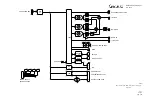
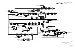
LOC and G/S Operation
For Localizer (LOC) and Glideslope (G/S) operation, AF Gen #1 is set to 90 Hz and AF
Gen #2 is set to 150 Hz. The modulation attenuator DAC’s and corresponding offset
DAC’s are set, the bearing counter is set and both reset signals are removed
simultaneously.
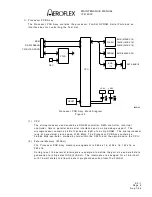
VOR Operation
In VOR mode, AF Gen #1 uses the 983.04 kHz clock and AF Gen #2 uses the 24.576
MHz clock to reduce the quantization error due to the output DAC of the DDS. AF Gen
#2 is programmed to 9960 Hz output frequency with 0 phase offset and AF Gen #1 is
programmed to 30 Hz output frequency with 0 phase offset. The FM modulation, on
top of the 9960 Hz, is generated by a 16 bit, 101 entry table in RAM in the FPGA. The
entries in the table are output at a 3 kHz rate to modify the output frequency of the
DDS to generate the 30 Hz FM reference signal for the VOR signaling format.
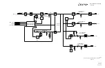
Bearing/Phase Shift Counter
The bearing/phase shift circuitry puts both AF Gen #1 and AF Gen #2 in reset mode,
programmed for a particular frequency, then releases both AF Gen #1 and AF Gen #2
from reset at a fixed interval to set the phase relationships of the two audio signals.
Once AF Gen #1 and AF Gen #2 are released from reset, the relative phase remains
the same. The timing relationship between the two reset signals is controlled by the
bearing/phase shift counter. The bearing counter is used for VOR, ILS and GS modes.
The bearing counter delays the start of AF Gen #2 to cause a phase shift between the
30 Hz Reference and the 30 Hz Variable signal that corresponds to a particular
bearing setting. The counter is programmable in 0 to 3600, that corresponds to a
heading from 0 to 360 degrees in 0.1 degree steps. For VOR mode, a setting of 1800
is equal to 0 degrees TO heading, and a setting of 0000 is equal to 0 degrees FROM
heading. For ILS and G/S mode, the Bearing counter delays the start of the 150 Hz
signal in relationship to the 90 Hz signal. In this mode, 1 degree (bearing counter
setting of 10) causes a 5 degree delay in the output of the 150 Hz signal (5 degrees at
150 Hz). Adjustments are in 5 degree actual increments up to a maximum of 120
actual degrees (bearing counter setting of 240). Display indicate actual degrees of
phase shift.
(6) I
2
C Bus
The I
2
C bus is a two-wire bi-directional serial bus that is used to communicate with
several assemblies in the 4000. All assemblies are connected in parallel to the clock
and data lines, following a master/slave type protocol.
(7) USB
The Multi-Function PCB Assy contains a Universal Serial Bus host and device
controller, performing both host and peripheral functions, to communicate with an
external PC for remote control or software downloads.
The USB controller is a 16-bit device with two address lines. The address inputs are
used for selecting command or data for the HC or DC registers. The USB two interrupt
outputs, one for the host and one for the device, are connected to the interrupt
register in the FPGA.
(8) RS-232
The Multi-Function PCB Assy contains an RS-232 level translator. The level translator
is a +3.3 V device for performing the TTL to RS-232 level translation. The level
translator has driver disable and shutdown control pins for low power modes.
Summary of Contents for IFR 4000
Page 1: ...NAV COMM Test Set Maintenance Manual 1002 5600 4P0 IFR 4000...
Page 3: ...MAINTENANCE MANUAL IFR 4000 FOR QUALIFIED SERVICE PERSONNEL ONLY...
Page 4: ...MAINTENANCE MANUAL IFR 4000 THIS PAGE INTENTIONALLY LEFT BLANK...
Page 6: ...MAINTENANCE MANUAL IFR 4000 THIS PAGE INTENTIONALLY LEFT BLANK...
Page 12: ...MAINTENANCE MANUAL IFR 4000 INTRODUCTION Page 2 Aug 1 04 THIS PAGE INTENTIONALLY LEFT BLANK...
Page 32: ...MAINTENANCE MANUAL IFR 4000 2 2 1 Page 14 Aug 1 04 THIS PAGE INTENTIONALLY LEFT BLANK...
Page 34: ...MAINTENANCE MANUAL IFR 4000 2 2 1 Page 16 Aug 1 04 THIS PAGE INTENTIONALLY LEFT BLANK...
Page 42: ...MAINTENANCE MANUAL IFR 4000 2 2 2 Page 8 Aug 1 04 THIS PAGE INTENTIONALLY LEFT BLANK...
Page 108: ...MAINTENANCE MANUAL IFR 4000 2 2 4 Page 2 Aug 1 04 THIS PAGE INTENTIONALLY LEFT BLANK...
Page 160: ...MAINTENANCE MANUAL IFR 4000 2 2 4 Page 54 Aug 1 04 THIS PAGE INTENTIONALLY LEFT BLANK...
Page 166: ...MAINTENANCE MANUAL IFR 4000 2 3 1 Page 6 Aug 1 04 STEP PROCEDURE 4 Remove the Fuse...
Page 186: ...MAINTENANCE MANUAL IFR 4000 APPENDIX B Page 2 Aug 1 04 THIS PAGE INTENTIONALLY LEFT BLANK...
Page 188: ...MAINTENANCE MANUAL IFR 4000 APPENDIX C Page 2 Aug 1 04 THIS PAGE INTENTIONALLY LEFT BLANK...
Page 200: ...MAINTENANCE MANUAL IFR 4000 APPENDIX D Page 12 Aug 1 04 THIS PAGE INTENTIONALLY LEFT BLANK...
Page 206: ...MAINTENANCE MANUAL IFR 4000 APPENDIX E Page 6 Aug 1 04 THIS PAGE INTENTIONALLY LEFT BLANK...


