MAINTENANCE MANUAL
IFR 4000
2-2-2
Page 1
Aug 1/04
2. Troubleshooting Procedures
A. Guidelines
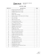
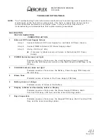
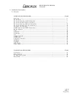
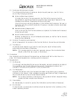
Troubleshooting is divided into a Symptom Index and a Troubleshooting Table.
The Troubleshooting Table lists common malfunctions which may occur during operation of
Test Set. Perform tests/inspections and corrective actions in order listed.
NOTE:
This manual cannot list all malfunctions that may occur, nor all tests or inspections
and corrective actions.
NOTE:
If a malfunction is not listed or is not corrected by listed corrective actions, the
troubleshooting technique (the formulation of a logical approach in locating the
source of trouble) is left to the technician’s discretion.
Following is a list of aids to be used when troubleshooting the Test Set:
O
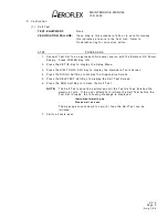
The Test Set has a built-in Self Test to assist the technician in troubleshooting.
O
Many problems on Test Sets in service are caused by corrosion. Sometimes removing
and reseating an affected cable or circuit card corrects the malfunction. Cleaning
connector and/or switch contacts with alcohol repairs many types of digital and analog
circuit malfunctions.
O
The following inspection procedures are used to locate obvious malfunctions with the
Test Set:
O
Inspect all external surfaces of the Test Set for physical damage, breakage, loose or
dirty contacts and missing components.
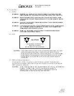
CAUTION:
DO NOT DISCONNECT OR REMOVE ANY BOARD ASSEMBLIES IN THE
TEST SET UNLESS THE UNIT IS REMOVED FROM ANY AC POWER
SOURCES. SOME ASSEMBLIES CONTAIN DEVICES THAT CAN BE
DAMAGED IF THE ASSEMBLY IS REMOVED WHEN POWER IS ON.
SEVERAL COMPONENTS, INCLUDING MOS DEVICES, CAN BE
DAMAGED BY ELECTROSTATIC DISCHARGE. USE CONDUCTIVE
FOAM AND GROUNDING STRAPS WHEN SERVICING IS REQUIRED
AROUND SENSITIVE COMPONENTS. USE CARE WHEN UNPLUGGING
ICS FROM HIGH-GRIP SOCKETS.
O
Inspect printed circuit board surfaces for discoloration, cra cks, breaks and warping
and printed circuit board conductors for breaks, cra cks. cuts, erosion or looseness.
O
Inspect all assemblies for burnt or loose components.
O
Inspect all chassis-mounted components for looseness, breakage, loose contacts or
conductors.
O
Inspect Test Set for disconnected, broken, cut, loose or frayed cables or wires.
Summary of Contents for IFR 4000
Page 1: ...NAV COMM Test Set Maintenance Manual 1002 5600 4P0 IFR 4000...
Page 3: ...MAINTENANCE MANUAL IFR 4000 FOR QUALIFIED SERVICE PERSONNEL ONLY...
Page 4: ...MAINTENANCE MANUAL IFR 4000 THIS PAGE INTENTIONALLY LEFT BLANK...
Page 6: ...MAINTENANCE MANUAL IFR 4000 THIS PAGE INTENTIONALLY LEFT BLANK...
Page 12: ...MAINTENANCE MANUAL IFR 4000 INTRODUCTION Page 2 Aug 1 04 THIS PAGE INTENTIONALLY LEFT BLANK...
Page 32: ...MAINTENANCE MANUAL IFR 4000 2 2 1 Page 14 Aug 1 04 THIS PAGE INTENTIONALLY LEFT BLANK...
Page 34: ...MAINTENANCE MANUAL IFR 4000 2 2 1 Page 16 Aug 1 04 THIS PAGE INTENTIONALLY LEFT BLANK...
Page 42: ...MAINTENANCE MANUAL IFR 4000 2 2 2 Page 8 Aug 1 04 THIS PAGE INTENTIONALLY LEFT BLANK...
Page 108: ...MAINTENANCE MANUAL IFR 4000 2 2 4 Page 2 Aug 1 04 THIS PAGE INTENTIONALLY LEFT BLANK...
Page 160: ...MAINTENANCE MANUAL IFR 4000 2 2 4 Page 54 Aug 1 04 THIS PAGE INTENTIONALLY LEFT BLANK...
Page 166: ...MAINTENANCE MANUAL IFR 4000 2 3 1 Page 6 Aug 1 04 STEP PROCEDURE 4 Remove the Fuse...
Page 186: ...MAINTENANCE MANUAL IFR 4000 APPENDIX B Page 2 Aug 1 04 THIS PAGE INTENTIONALLY LEFT BLANK...
Page 188: ...MAINTENANCE MANUAL IFR 4000 APPENDIX C Page 2 Aug 1 04 THIS PAGE INTENTIONALLY LEFT BLANK...
Page 200: ...MAINTENANCE MANUAL IFR 4000 APPENDIX D Page 12 Aug 1 04 THIS PAGE INTENTIONALLY LEFT BLANK...
Page 206: ...MAINTENANCE MANUAL IFR 4000 APPENDIX E Page 6 Aug 1 04 THIS PAGE INTENTIONALLY LEFT BLANK...


