Chapter 2 The AP340 Platform
20
Aerohive
Ethernet and Console Ports
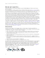
The AP340 has two RJ-45 10/100/1000Base-T/TX Ethernet ports and an RJ-45 console port.
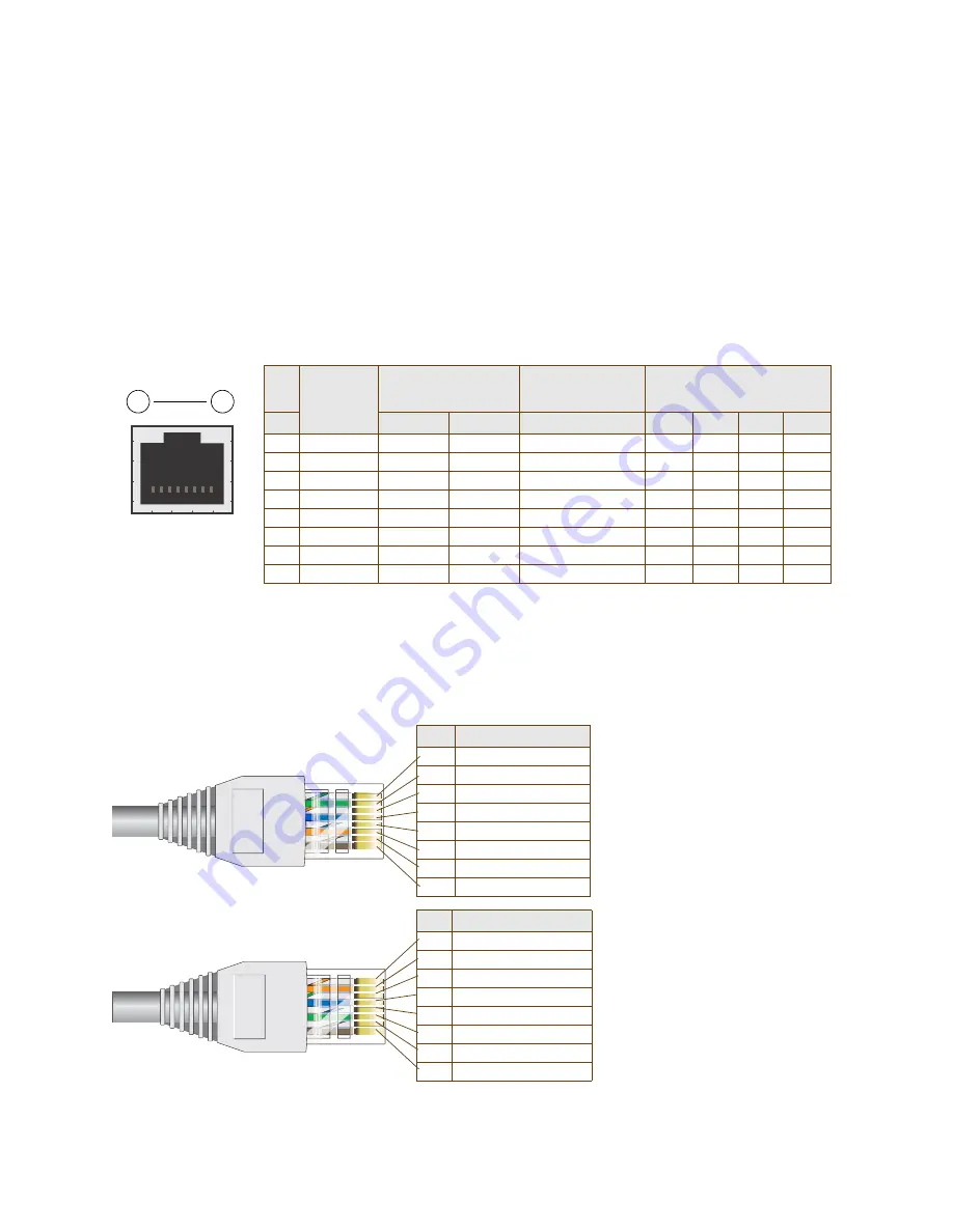
The pin assignments in the PoE (Power over Ethernet) Ethernet ports follow the TIA/EIA-568-B standard (see
). The ports accept standard types of Ethernet cable—cat3, cat5, cat5e, or cat6—and can receive power
from power-sourcing equipment (PSE) that is 802.3af-compatible. If you use cat5, cat5e, or cat6 cables, the
AP340 can also support 802.3at-compliant PSE. Such equipment can be embedded in a switch or router, or it
can come from purpose-built devices that inject power into the Ethernet line en route to the HiveAP. Because
the PoE ports have autosensing capabilities, the wiring termination in the Ethernet cable can be either
straight-through or cross-over.
Figure 2 PoE wire usage and pin assignments
ETH0
Pin
T568A Wire Color
1
White/Green
2
Green
3
White/Orange
4
Blue
5
White/Blue
6
Orange
7
White/Brown
8
Brown
(View of the ETH0 PoE
Port on the AP340)
8
1
Pin numbers
Pin
T568B Wire Color
1
White/Orange
2
Orange
3
White/Green
4
Blue
5
White/Blue
6
Green
7
White/Brown
8
Brown
T568A-terminated Ethernet
cable with an RJ-45 connector
Data Signal
802.3af Alternative A
(data and power on the
same wires)
802.3af Alternative B
(data and power on
separate wires)
802.3at wring options
Pin
MDI
MDI-X
MDI or MDI-X
1
2
3
4
1
Tr
DC+
DC–
– – –
DC1+
DC1–
DC1+
DC1–
2
Transmit -
DC+
DC–
– – –
DC1+
DC1–
DC1+
DC1–
3
R
DC–
DC+
– – –
DC1–
DC1+
DC1–
DC1+
4
(unused)
– – –
– – –
DC+
DC2+
DC2+
DC2–
DC2–
5
(unused)
– – –
– – –
DC+
DC2+
DC2+
DC2–
DC2–
6
Receive -
DC–
DC+
– – –
DC1–
DC1+
DC1–
DC1+
7
(unused)
– – –
– – –
DC–
DC2–
DC2–
DC2+
DC2+
8
(unused)
– – –
– – –
DC–
DC2–
DC2–
DC2+
DC2+
MDI = Medium dependent interface for straight-through connec ions
MDI-X = Medium dependent interface for cross-over (X) connections
The PoE ports are auto-sensing and can automatically adjust to transmit and receive data over straight-through or
cross-over Ethernet connections. Likewise, they can automatically adjust to 802.3af Alternative A and B power delivery
methods. Furthermore, when the Alternative A method is used, the ports automatically allow for polarity reversals
depending on their role as either MDI or MDI-X. In 802.3at, the 1/2 and 3/6 wire pairs connect to DC source 1 and 4/5
and 7/8 pairs to DC source 2 in PSE. Although the exact polarity depends on the PSE design, the AP340 Ethernet
ports can support all possible options.
T568B-terminated Ethernet
cable with an RJ-45 connector
T568A and T568B are two
standard wiring termination
schemes. Note that the only
difference between them is that
the white/green + solid green pair
of wires and the white/
solid orange pair are reversed.
For straight-through Ethernet
cables—using either the T568A or
T568B standard—the eight wires
terminate at the same pins on
each end.
For cross-over Ethernet cables,
the wires terminate at one end
according to the T568A standard
and at the other according to
T568B.
Summary of Contents for Aerohive APs
Page 1: ...Aerohive Hardware Reference Guide ...
Page 7: ...Contents 6 Aerohive ...
Page 17: ...Chapter 1 The AP330 and AP350 Platforms 16 Aerohive ...
Page 47: ...Chapter 3 The AP320 Platform 46 Aerohive ...
Page 61: ...Chapter 4 The AP170 Platform 60 Aerohive ...
Page 91: ...Chapter 8 The High Capacity HiveManager 90 Aerohive ...


