Hardware Reference Guide
21
AP340 P
RODUCT
O
VERVIEW
Smart PoE
The AP320 and AP340 apply the Aerohive concept of smart PoE to adjust power consumption as necessitated
by varying levels of available power. The AP340 supports PoE on both its ETH0 or ETH1 interfaces and can
draw power through either one or through both simultaneously. Based on the available power that the AP340
detects, it manages its internal power use by making the following adjustments:
•
No adjustments are needed when the power level is 20 W (watts) or higher. If the available power drops to
a range between 18 and 20 W, the HiveAP disables its ETH1 interface, assuming that it is drawing power
through its ETH0 interface. If it is drawing power solely through its ETH1 interface, then it disables its
ETH0 interface instead.
•
If the power level drops to the 15 – 18 W range, the AP340 then switches from 3x3 MIMO (Multiple In,
Multiple Out) to 2x3 (see
"Configuring Antennas" on page 25
•
In rare cases when the power drops between 13.6 and 15 W and further power conservation is necessary,
the HiveAP reduces the speed on its active Ethernet interface—ETH0 or ETH1—from 10/100/1000 Mbps to
10/100 Mbps.
•
Finally, in the event that there is a problem with the PoE switch or Ethernet cable and the power falls
between 0 and 13.6 W, the HiveAP disables its wireless interfaces and returns its ETH0 and ETH1
interfaces to 10/100/1000 Mbps speeds.
Through the application of smart PoE, the AP340 can make power usage adjustments so that it can continue
functioning even when the available power level drops.
Aggregate and Redundant Interfaces
By default ETH0 and ETH1 act as two individual Ethernet interfaces. When both interfaces are connected to the
network and are in backhaul mode, the HiveAP transmits broadcast traffic only through ETH0. The HiveAP
transmits broadcast traffic through ETH1 only when ETH0 does not have network connectivity. When both
Ethernet interfaces are connected to the network and are in access mode, then the HiveAP transmits broadcast
traffic through all the access interfaces: ETH0, ETH1, and all wireless subinterfaces in access mode.
In addition to using ETH0 and ETH1 as individual interfaces, you can combine them into an aggregate interface
(agg0) to increase throughput, or combine them into a redundant interface (red0) to increase reliability. The
logical red0 and agg0 interfaces support all the settings that you can configure for Ethernet interfaces except
those pertaining to physical link characteristics such as link speed. See the sections below for configuration
information.
Aggregate Interface
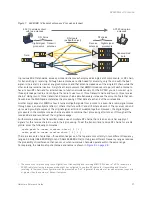
You can increase throughput onto the wired network by combining ETH0 and ETH1 into a single logically
aggregated interface called "agg0". The aggregate interface effectively doubles the bandwidth that each
physical interface has when used individually. In this configuration, both Ethernet ports actively forward traffic,
the HiveAP applying an internal scheduling mechanism based on the source MAC address of each packet to
send traffic through the aggregate member interfaces. To configure an aggregate interface, enter the following
commands:
interface eth0 bind agg0
interface eth1 bind agg0
In addition to configuring the HiveAP, you must also configure the connecting switch to support EtherChannel.
For example, the following commands bind two physical Ethernet ports—0/1 and 0/2—to the logical interface
port-channel group 1 on a Cisco Catalyst 2900 switch running Cisco IOS 12.2:
Switch#conf t
Switch(config)#interface port-channel 1
Switch(config-if)#switchport mode access
Summary of Contents for Aerohive APs
Page 1: ...Aerohive Hardware Reference Guide ...
Page 7: ...Contents 6 Aerohive ...
Page 17: ...Chapter 1 The AP330 and AP350 Platforms 16 Aerohive ...
Page 47: ...Chapter 3 The AP320 Platform 46 Aerohive ...
Page 61: ...Chapter 4 The AP170 Platform 60 Aerohive ...
Page 91: ...Chapter 8 The High Capacity HiveManager 90 Aerohive ...

